|
#451
 Thu 13 March 2014, 21:01
|
|||
|
|||
|
Congrats to #117 from #101.
Great job!!! 
|
|
#452
Thu 13 March 2014, 21:09
|
|||
|
|||
|
When you came on board Darren I thought I could get mine together before you, then life happened, well here I am 16 behind, oh well. I still got it done though. Thanks again.
|
|
#453
Thu 13 March 2014, 21:21
|
|||
|
|||
|
A finished, functioning machine that will chug away for hours on end with no complaints is the only result that matters. Timeframes mean nothing.
|
|
#454
Fri 14 March 2014, 03:15
|
|||
|
|||
|
Well done #117.
Welcome to a new world.
|
|
#455
Fri 14 March 2014, 03:59
|
|||
|
|||
|
Thanks Al.
Darren you are absolutely correct. I know just how it works for me, if I don't finish it now and just run with what I got, things will go along, I'll forget what I learned about the set up (out of sight, out of mind kind of thing) then 6 months, a year down the road it still won't be done and I'll wish I had done it when I started. Now that its running, time frames mean a lot, like I said I've got customers beating the door down, first job, 10 contemporary clock cases. Next speaker parts prototyping and fulfillment, then a bunch of other parts, violin faces and backs, signage somewhere in there. and the list goes on. Just hope I can get the software thing worked out quickly enough. I should have been playing with it much sooner, but no time. I will be asking questions, a lot of questions.
|
|
#456
Fri 14 March 2014, 05:22
|
|||
|
|||
|
Does anyone have a recommended feed rate and speed for aluminum? I know that some are cutting it with little trouble. Just don't want to break the first bit without atleast starting somewhere close to the correct numbers. The web keeps turning up mills and the onsrud guide tells little on aluminum. I'm trying to cut out the belt reduction plates for #117.
Edit: I think I got it, I had to find the recommended chip load first, and have the formulas for the rest. Last edited by Tom Ayres; Fri 14 March 2014 at 05:35..
|
|
#457
Fri 14 March 2014, 07:58
|
|||
|
|||
|
Congratulations and good luck.
|
|
#458
Fri 14 March 2014, 08:41
|
|||
|
|||
|
Thanks Paulo

|
|
#459
Fri 14 March 2014, 08:54
|
|||
|
|||
|
Congrats on a fine build Tom!

|
|
#460
Fri 14 March 2014, 09:28
|
|||
|
|||
|
Thanks Heath, not quite done with everything but good enough to run.
|
|
#461
Fri 14 March 2014, 14:39
|
|||
|
|||
|
Some additional work done this afternoon. Now that I know how to post these pics thanks to Pete, you'll see a lot more.
[IMG] 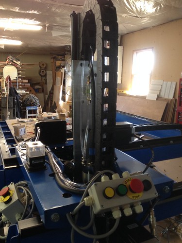 Echain on Z by ThomasAyresJr, on Flickr[/IMG] water lines and power to the pump and fan and proxy connection. [IMG] 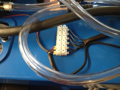 Proxy & 12vdc Power by ThomasAyresJr, on Flickr[/IMG] The proxy is poking its head out [IMG] 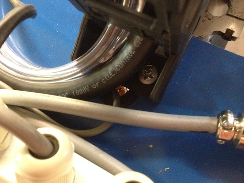 Echain Wire by ThomasAyresJr, on Flickr[/IMG] Y car and z 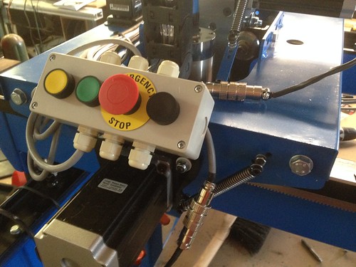 Control Box Y Car by ThomasAyresJr, on Flickr  Fan and Pump by ThomasAyresJr, on Flickr[/IMG] 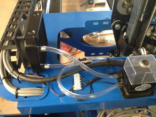 Y Car by ThomasAyresJr, on Flickr
|
|
#462
Fri 14 March 2014, 15:03
|
|||
|
|||
|
Congratulations on your build...keep us up to date with what your cutting.
cheers Andrew
|
|
#463
Fri 14 March 2014, 15:28
|
|||
|
|||
|
Thanks Andrew I certainly will.
|
|
#464
Sat 15 March 2014, 05:52
|
|||
|
|||
|
Here is some of the fan and pump pics from the rear of the y-car, thought someone you reference any detail they needed.
[IMG]  Fan and Pump by ThomasAyresJr, on Flickr[/IMG] Another view of the spindle mount and plumbing [IMG] 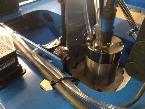 Water Lines by ThomasAyresJr, on Flickr[/IMG] The pump is one of those cheap pumps you find on ebay for next to nothing, I ran it for the first time yesterday to prime it and found it has a blue LED up lighting from the bottom to help you see that its on and see water levels. Kinda cool, but still cheap. It moves the water just fine but not with any great urgency, I'm afraid it may not cool fast enough, I'll do some temperature tests later once its really running something other than a roadrunner. Today I'll nail down the z proxy mount, the wiring is done for it (see terminal block mounted on y-car, mounted with VHB tape, works great). I'll also attempt to get the zeroing plate situated. I found a 'Blue Screen' zeroing macro for mach on cnczone I think I'll try. Here is is if anyone wanted to take a look http://www.cnczone.com/forums/mach-w...ification.html
|
|
#465
Sat 15 March 2014, 06:54
|
|||
|
|||
|
Is there a reccommended break-in procedure for spindles? Or maybe start-up routine I should follow? I vaguely remember someone doing something.
|
|
#466
Sat 15 March 2014, 10:32
|
|||
|
|||
|
Your water flow does not need to be a lot. Too high of a pressure and water being forced instead of flowing and you will start to form condensation on the inside and outside of the housing which is worse than motor heating. As long as it is a full steady stream of water you will be okay.
Run it at a low speed for several minutes to warm up the grease in the bearings. Another note is you should have your pulley setting set for high and low end so you so not mistakenly input 1500 instead of 15000 and Mach will default to the lowest speed setting.
|
|
#467
Sat 15 March 2014, 11:17
|
|||
|
|||
|
Doing a quick search on one site has some specific recommendations for warming up a spindle that has been out of use for a long time.
http://www.pdscolombo.com/spindle-maintenance I also wonder what the thermal dissipation is for these spindles . I can not seem to find anything documented for my spindle or others out there. Last edited by dbinokc; Sat 15 March 2014 at 11:19..
|
|
#468
Sat 15 March 2014, 11:40
|
|||
|
|||
|
Builder's Log Update
Tom,
Congratulations on your build and on earning Serial # 117. Here is the Updated Builder's Log with your entry added. Please let me know if you have any changes for the entry. I guessed at the dimensions base on an early statement you made about building either a 5' X 10' or 5' X 12' machine.
|
|
#469
Sat 15 March 2014, 11:48
|
|||
|
|||
|
Thanks John, there is a change, the table dims are 144 by 60
DB, I'll check it out Thanks again Pete. There's certainly not a bunch of pressure to worry about.
|
|
#470
Sat 15 March 2014, 12:15
|
|||
|
|||
|
Tom,
Great job on 117, now all you need is a product to make and start running this baby two shifts per day. I'm still working on it.
|
|
#471
Sat 15 March 2014, 13:19
|
|||
|
|||
|
Thanks Tom,
Changed dimensions to 144" X 60"
|
|
#472
Sat 15 March 2014, 14:50
|
|||
|
|||
|
Alright I've got no proxy sensing going on, they are connected right so I checked voltage and found that when closed roughly ~13v, when open about 4.85v. I think that its not dropping enough for the bob to sense the change. Should I add a resistor to the circuit? Or should I change the incoming voltage to 24v?
Last edited by Tom Ayres; Sat 15 March 2014 at 14:51.. Reason: added question
|
|
#473
Sat 15 March 2014, 14:53
|
|||
|
|||
|
Armando, the whole idea is to work less
 , make more! , make more!
|
|
#474
Sat 15 March 2014, 18:44
|
|||
|
|||
|
Tom, which prox switches are you using? When they open it should be 0VDC. Is your dc common bonded to ground?
|
|
#475
Sat 15 March 2014, 19:05
|
|||
|
|||
|
Ground from BOB. The bob pins led brightly lighted when active and ever so slightly dims when tripped (of coarse there's still power, but should should drop enough). Should I find a true ground? Maybe its a configuration in mach, I got the x-a working, but everything looks correct. Funny thing though, auto configuration doesn't work. Diagnostics doesn't see either the y or z so I swapped them for new ones, same result. I'm almost thinking reloading mach.
Edit: You asked what proxys, they are npn no 6-30 volt. I can shoot a picture for you and post if you'd like Last edited by Tom Ayres; Sat 15 March 2014 at 19:08..
|
|
#476
Sat 15 March 2014, 19:13
|
|||
|
|||
|
All power supply commons should be bonded to ground. It makes reading the voltages more accurate from ground. Unless you need a floating voltage it is best to bond the common
|
|
#477
Sat 15 March 2014, 19:22
|
|||
|
|||
|
I thought the '12u' 'pin' and gnd' on the bob are the connection points for the proxys, are you saying that the pins gnd is too isolated for its own use, I guess I could try another supply and ground. I do have the 12 vdc from the PS and a separate din mounted 24v ps which I haven't used yet.
Edit: Part of the original problem was the proxys were mounted too close to the rail. I found the sweet spot around 3.5 mm off the surface of the steel. Edit again: The x-a are wired parallel while the others are direct Last edited by Tom Ayres; Sat 15 March 2014 at 19:27..
|
|
#478
Sat 15 March 2014, 19:30
|
|||
|
|||
|
The '+', '-" and 'gnd' are separate entities on a power supply. The ground is chassis ground. Are you using the +12 from the BOB?
|
|
#479
Sat 15 March 2014, 19:46
|
|||
|
|||
|
Yes, having read the bob manual is the reason.
I'm heading out to the shop now, I'll check back in a bit.
|
|
#480
Sat 15 March 2014, 20:23
|
|||
|
|||
|
I am following you now. I am using the method used on pg 22 of rev b or pg 23 of rev c for the 126. I did not use the onboard power but an external power supply. Does sound like a pull down problem but it could be something else. Another thing is the switch might be bleeding to the steel of the machine. Remove the switches from there holders and place on a non conductive surface and see how the action of the LED works.
|
 |
|
|
 Similar Threads
|
||||
| Thread | Thread Starter | Forum | Replies | Last Post |
| Cutting sign vinyl with your MM | smreish | Cutting various materials - bit selection, feeds, speeds | 5 | Thu 17 March 2016 03:33 |
| Problems working the end of some Ballscrews | coinhunter | Miscellaneous / General / Whatever / Catchall | 5 | Thu 21 July 2011 14:06 |
| Working Out The Table Plan | dakmonf | Introduce yourself and start planning | 32 | Wed 30 June 2010 11:59 |
| Power Contactor Not Working | Regnar | Troubleshooting | 28 | Sat 10 April 2010 12:38 |
| Vinyl Cutting with MM - Drag knife attachment for router | Kobus_Joubert | 50. Toolheads | 17 | Thu 04 June 2009 01:27 |


