|
#1
 Mon 29 October 2012, 06:35
|
|||
|
|||
|
Inconsistant cutting errors.
We are having issues with getting the mech mate we have bought up and running properly as it is cutting quite inconsitantly. We really need to get this working asap (like 2 weeks ago) as we have work for it backing up now.
So any help and suggestions are greatfully welcomed. Firstly i will give you a run down on the machine. Right we bought this 1200x1200 mech mate second hand on ebay from a sign company who bought it from the builder. When we bought it we realised it may take some sorting out being a self build machine, but after studying this forum thought it had the potential to be a good machine. Now that we have it we are fairly certain that it has never actually been got running propperly (and we think it was built 07-08 from some of the recipts that came with it). When we got the machine back to our workshop we plugged it strait into our other machines computer which already had mach 3 installed and started it up to give it a little shake down and well thats what it did "shake". The base table was obviously very underbuilt with fairly poor welding and when we moved the gantry it wobbled like a jelly in an earthquke. So the first thing we have done is add a load of trianglulation to the base using 18mm birch ply (as we dont have welding facilities). With this we managed to get the machine fairly stable now with only the slightest of movement when under hard turns. We then cleeaned and re-lubricated all the moving parts and they all seem ok and everything rolls nice and free. The rails Have not been ground very neatly or evenly but it doesn't visually seem to effect the way it moves. So we turned to the electronics next. It was only fitted with a very early model CNC4PC C1 control board. So we have upgraded this to the C32+ smooth stepper boards. We did this so that we could intall a little asus all in one PC into the control box. The machine came with Motion control stepper drivers - MSD556, Motion Control Stepper motors - FL86STH65 and 1 Motion control power supply - PS407 (40v @ 7a). We have left these in for now but realise these being under speced for a machine of this mass could possibly be the cause of our issue. We next fitted the C16 opto isolated limit switches. Then we thought we would be ready to test the machine and start setting it up. Wrong! The Machine came fitted with a porter cable router fitted and on attempting some cuts at varying feeds, speed, acceleration and plunge rates it was evident that this was not going to be upto the job. So we went and bought a 3kw Chinese air cooled spindle (square type) + VFD from a local cnc supplier, got a new mounting plate machined for us and got this fitted. So the machine no longer wobbles or shakes, it has a "decent" spindle and vfd and better control system. When moving the gantry round on the joystick (xbox controller) it all seems to run quickly and smoothly (and suprisingly quitely). We still need to fit e-chain and route the cabling properly as well as fit a few e-stops but other than that it seems about ready for testing. So we started doing some movement calibrations to check the distance accuracy. We have done this using some engineering bocks that were acurate to around 5 thousands of a mm. We then used a dial guage on each axis to check the correcsponding movement. We appear to have got it to within a reapeatable tollerance of aound 0.05mm over a 400mm length on all axis. Mach settings are 25.064 steps per rev 8000mm/min 700mm/s/s Test cuts were made with 1/4" compression cutter 6mm depth cut at 2767mm/min in birch ply 24mm we ran a basic program with a square with a diamond inside of it, a spline, a circle, a diagonal line and a square. This is the result. 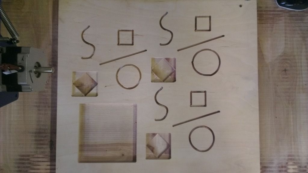 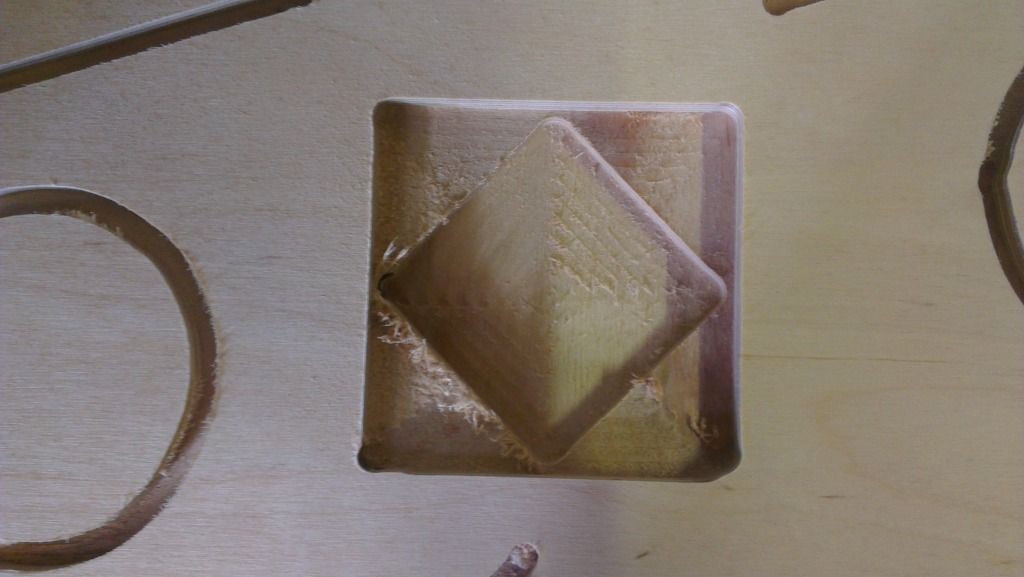 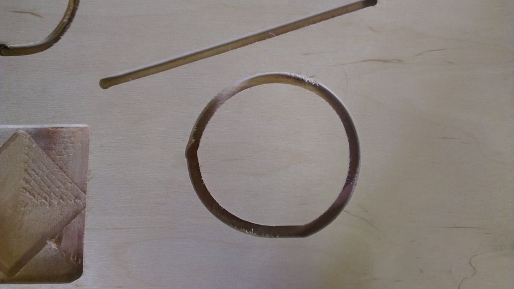 Some Photos of the machine. 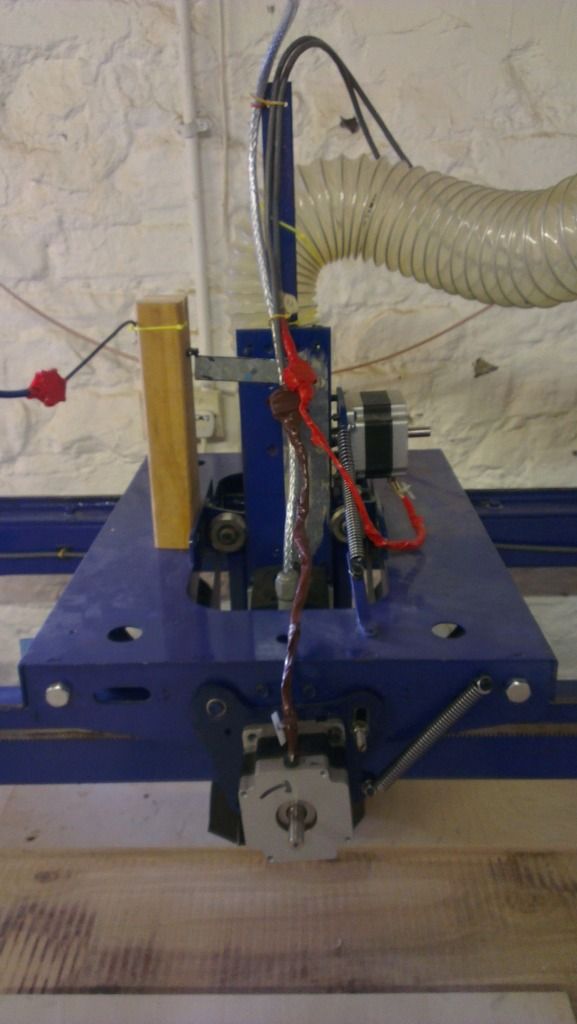 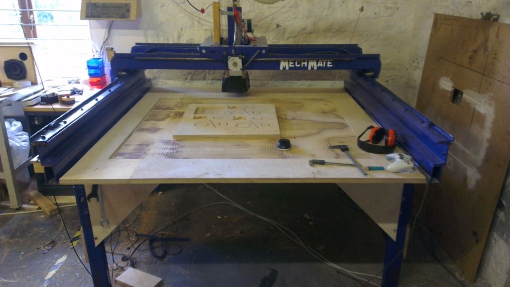 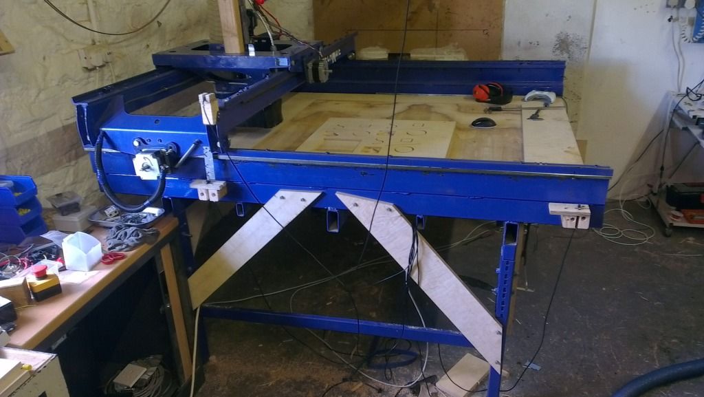 
|
|
#2
Mon 29 October 2012, 06:41
|
|||
|
|||
|
Mechanical Slop. It truly looks like grub screws loose on the shaft or z plate shifting during transitions.
Did you grind a little flat spot at 0 and 90 degree's on motor shaft and install 2 grub screws on the pinion?
|
|
#3
Mon 29 October 2012, 06:56
|
|||
|
|||
|
We did not, the pinion does have 2 grub screws at 90 degrees but the motor shaft does not have any flat spots. After reading several of the trouble shooting threads I thought this may be a possibility. I actually tried unhooking the springs thus releasing the pinion from the rack and gave it a tug with a set of large pliers (As suggested by gerald in another thread) but the motor shaft just turns really quite easily rather than the pinion, this is with the holding torque on.
|
|
#4
Mon 29 October 2012, 07:02
|
|||
|
|||
|
But your turning the pinion on a motor shaft with no load. I bet if you tried the same thing with the motor active and pliers holding to "stall" the motor you would have movement.
It really looks like mechanical slop.
|
|
#5
Mon 29 October 2012, 07:04
|
|||
|
|||
|
Another thing I should add is that the motors installed on the machine actually have 12mm shafts not 1/2inch and the pinions are obviously half inch. Who ever fitted them
has fitted an extremely thin strip of brass wrapped around the shaft to act as a spacer of sorts. This does give them a very slightly un-even rotation along the rack. From our measurement tests this does not seem to have much effect. We were a little bit worried about removing the pinion as we think the brass sheet may disintegrate, leaving an extremely wobbly pinion?
|
|
#6
Mon 29 October 2012, 07:07
|
|||
|
|||
|
The motors were turned on at the time. Is there any way to get the motors to put more of a holding force on? As without too much of a force the shaft turned so couldn't really test how tight the pinion was.
|
|
#7
Mon 29 October 2012, 07:10
|
|||
|
|||
|
By the way thanks for the quick reply Sean. Much appreciated.
|
|
#8
Mon 29 October 2012, 07:36
|
|||
|
|||
|
The pinions being the wrong dia could be an issue too.
Did you replace the pinions or are they still shimmed? Do you have a tig welder? You could always just "tack" a spot on the end of the shaft and pinion as an absolute last resort. A quick grind and your back to new again.
|
|
#9
Mon 29 October 2012, 07:50
|
|||
|
|||
|
The slight difference in shaft diameter doesn't seem to be creating to much issue from what we can see. As when we did all of our setup measurements on each axis they were repeatable. The pinions are still shimmed as they were. We've been trying to avoid removing them in case the shimming falls apart. We did actually get a quote for new pinions from a gear company over here and it would cost another £160 (£40 each) which to be honest we don't really have spare. We don't have any form of metal welding but there are a few machine shops and garages around our industrial estate that might.
|
|
#10
Mon 29 October 2012, 07:53
|
|||
|
|||
|
The shim gives extra opportunities for slippage, and you say "motor shaft does not have any flat spots" - I think you have to take that apart and file two flats on the shaft. Shims are easy enough to replace - and you get to drink the beer out of the can first

|
|
#11
Mon 29 October 2012, 07:58
|
|||
|
|||
|
I have been thinking this. Right I'll be back shortly with an answer on if it is another case of slipping pinions.
|
|
#12
Mon 29 October 2012, 09:47
|
|||
|
|||
|
Well there are definite groove marks where it looks like the pinion may have been slipping on the motor shafts both on x and Y (still to get to the Z). I have just ground some flat spots on the shafts and my business partner Matt is making some new shims (using your method Brad nice one). So hopefully we will see a change in the cuts shortly,
Fingers Crossed eh!
|
|
#13
Mon 29 October 2012, 10:48
|
|||
|
|||
|
Well still not sorted. We have removed the pinions added flat spots and re-shimmed the motor shaft. But we are still seeing the same kind of issues. Another thing we noticed was the motors were moving about a little on the motor plates when the gantry was changing direction. So we tried tightening these up to pretty much fully locked and this helped a little but not much.
|
|
#14
Mon 29 October 2012, 11:40
|
|||
|
|||
|
Looking at the pic's. Doesn't look like your machine was built per plan. If the rest of the machine is as bad as the table looks, then I would be examming everything vs. the plans.
|
|
#15
Mon 29 October 2012, 11:42
|
|||
|
|||
|
Check for slop in the Z-Axis v-rollers in both possible dimensions. (As per Sean's original list of likely mechanical issues). Given what you've found so far, it's likely there are a few other issues to sort. I assume that both the car and the gantry roll smoothly along their entire paths with all four wheels down?
Oh, and I can't take credit for the beer can shims - that appeared years ago here on the forum.
|
|
#16
Mon 29 October 2012, 12:09
|
|||
|
|||
|
Just home now. But just before leaving work we started having a good look a the z slide and it does have play in one direction where one of the V-rollers doesn't actually contact it propperly and looking at the cuts it does seem that it may correlate to the change of direction. How do you adjust the v rollers, sorry not looked at that part of the drawings yet? Matt did purchase a set so we had a reference source (as well as you lovely lot of course).
Steve. The base was definately not built very well but the gantry all looks pretty much to the drawings from what I can tell so far. Also the gantry moves nice and smoothly to full extent in both X and Y with no binding of any kind. We have already been looking at getting a new 8 x 4 base made with some nice new v rails and a pully gear reduction system. Infact it was one of the first things we did, but it will simply have to wait until funds allow (and that requires the machine working pretty much with the spec it has now).
|
|
#17
Mon 29 October 2012, 12:24
|
|||
|
|||
|
Ideally, there are are offset bushings on those V-rollers that can be used to adjust them - a fraction of a turn should bring the V-roller closer or farther. But you'll first need to confirm that they are actually there on your machine - if not, then figure out how to add 'em.
|
|
#18
Mon 29 October 2012, 14:20
|
|||
|
|||
|
Well fingers crossed the builder realised there would be a need for adjustment post build. Will check first thing in the morning. Cheers for the help thus far. I know there is a good machine hiding in there somewhere.
|
|
#19
Tue 30 October 2012, 04:54
|
|||
|
|||
|
Put the machine one and then try shaking up the Z assy like Brad has already mentioned, if not you still have one final mod left to the mechmate - a Z axis with linear elements.
My best to you- been there - done that  http://www.mechmate.com/forums/showt...p?t=573&page=8
|
|
#20
Tue 30 October 2012, 11:30
|
|||
|
|||
|
Well! There were the right off set bushings on the Z slide rollers and that is now rigid in all axis. This has made another improvement to the cut quality but it has allowed us to see more issues this time with the machines rails "Hooray". The rails on the x axis are nice and strait but due to the poorly done griding of the rails we can see varying differences in height along its length. Both rails have there variations in different places and it means that at times the gantry is really only running on 2-3 rollers. This allows a little bit of slop in certain places. We have the same issue with the y car rails but it is actually more evedent here as in certain places along its length you can actually rock the Y car a little from corner to corner. Also one of the y rails was very slightly curved/bowed out at one end (although it didn't effect the car running in any noticable way). Matt managed to straiten this out quite easily.
Does any body know somewhere in the uk or eu to get Alu rails of the right type at a decent price as i feel this may be the only option?
|
|
#21
Tue 30 October 2012, 11:52
|
|||
|
|||
|
I would be tempted to try to knock the high spots off the rails, if you concur that you can manage to not make it any worse. Can you give us a close up photo of what a variation in the rails looks like? It might trigger some group ideas as to how to jig up to knock it down. Do you have a grinder, or a hand held sander?
|
|
#22
Tue 30 October 2012, 11:57
|
|||
|
|||
|
If the rail situation is not all that bad, it might just be a shimming issue perhaps?
|
|
#23
Tue 30 October 2012, 12:12
|
|||
|
|||
|
I like Heath's idea (you put shims under the bolts at the low spots). Also, note that there are slots to adjust the V-roller heights at at least one corner each of the gantry and car (can't remember exactly right now), so it may be that you can find a compromise setting that doesn't actually rock at any locations. Some combination of the roller height adjustment and shimming might get you home.
|
|
#24
Tue 30 October 2012, 13:23
|
|||
|
|||
|
Will try and take some photos of them in them morning. We have both grinders and sanders but I dont think I would want to try it free hand (as it has obviously been done). At a minimum I would want one of the rail grinding jigs to do it (we could potentially cut one using our other small axyz cnc machine). Personally i like the bolt on rail style more than ground (due to less possibility for error).
Heath: i will have a look to see if any of the low spot correlate with the bolt holes. my gut feeling is the variation is a bit to randomly spaced for it to work effectively. But all options are open and will be looked at! Brad: We'll ceratainly be giving it ago but again I feel that if we adjust it in one place to get it all level from one of the dips it will just rais another wheel at a high spot. I'm not sure if
|
|
#25
Wed 31 October 2012, 04:49
|
|||
|
|||
|
Irregular rails
Hi all
Thanks for your help so far. Here are some photos of the rails. 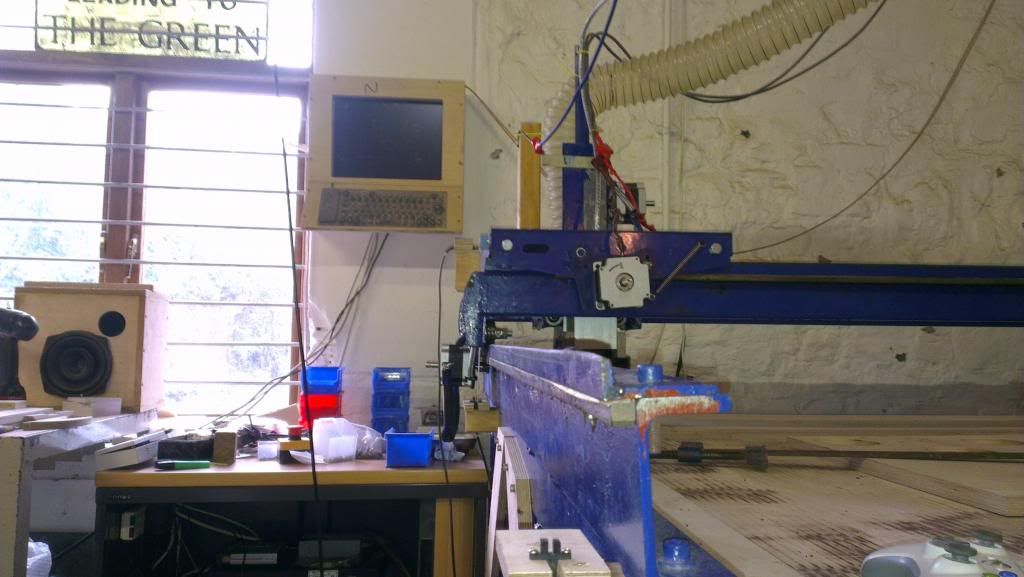 X-Rail 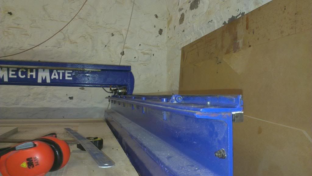 X-Rail 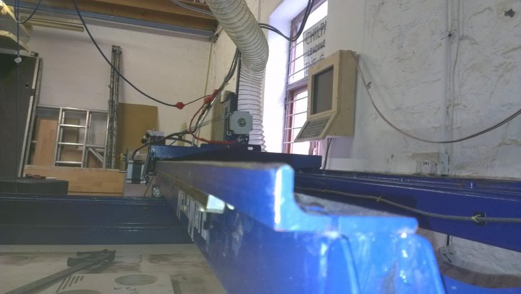 Y-Rail 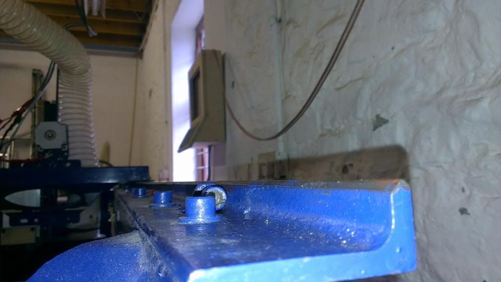 Y-Rail
|
|
#26
Wed 31 October 2012, 06:21
|
|||
|
|||
|
Nooooo !!
Such a shame, I can see nearly every error one could make in those shots. The beauty of the Mechmate Design is that the rails can be remade fairly cheaply as angle is inexpensive. Contact your seller and get the grinding skate they used or have a good look at the site and make your own version of it. I would recommend remaking the rails for several reasons. 1 - the cut off height is inconsistent 2 - the rails are not ground evenly on each side 3 - the ends of the rails are ground differently to the middle of the rails. The ends get like that because the maker did not allow and extra margin on the length when grinding the rails. If a bit extra has been ground then you can cut any wobbly bits off the ends. it is not my idea but I always push this one as it is just so good to "sand" the rails not "grind" the rails. Use a grinding disk as a backer for a course sanding disk and the removal rates will be so much faster as the sanding disk will not glaze. You can also use 120 grit as a final polishing pass, they will come up like a mirror. You are correct in saying that there is a good machine hiding in there somewhere and with some effort you will be rewarded. I note that the motors are smaller than spec so once your going you will need to slow the feed rates down a little to compensate. Check the wiring quality as well as the specification is generally for a braided shield on the motor wires. It may not be necessary to use shielded wire but if signal noise becomes an issue down the track it is always a good thing to know about. Good luck. Regards ross
|
|
#27
Wed 31 October 2012, 06:21
|
|||
|
|||
|
Well we are have now removed the y and z cars so that we could check the rails and bottom of tha y car spacers more carefull. The Y rails are not strait or perpendicular to x. So we have unbolted them now to get them strait and well go from there.
|
|
#28
Wed 31 October 2012, 06:28
|
|||
|
|||
|
HRoss,
I think your post came in just as I was writing that one. Its such a shame as we bought this one thinking it would be a quicker route than either getting a chinese machine or building our own. But I am fairly certain we could have had one built in a similar amount of time as we have now spent messing around with this one. But hay ho we live and learn.
|
|
#29
Wed 31 October 2012, 06:31
|
|||
|
|||
|
Oh yeah the motor wiring does all have braided shield which we have grounded.
We had this problem when we retro fitted our old AXYZ machine.
|
|
#30
Wed 31 October 2012, 10:53
|
|||
|
|||
|
Yeah, Ross covered it. Those rails are probably not worth trying to recover
 Great photos, though, they make the diagnosis easy. You guys should be in the home stretch now, though.
|
 |
|
|
 Similar Threads
|
||||
| Thread | Thread Starter | Forum | Replies | Last Post |
| Stepper motor refuses to turn - Wiring & jumper errors | Gato Richy | Troubleshooting | 31 | Thu 30 April 2009 23:56 |


