|
|||||||
| Register | Options | Profile | Last 1 | 3 | 7 Days | Search | Today's Posts | Mark Forums Read |
 |
|
|
Thread Tools |
|
#1
 Sat 18 December 2010, 20:44
|
|||
|
|||
|
Matty Zee Mach 3 Pluggin
Hey All,
Firstly let me thank Matty Zee for putting a lot of time and effort into developing the Mach3 pluggin. We have installed it and like many others we get all the right signs that its communicating with the VFD however shortly after starting the spindle everything locks up including Mach3 and the spindle continues to run until a system reboot has taken place. So my question is, has anybody else used the Matty Zee pluggin and if so did you have the same issues? did you get it working? and if so how? I notice on CNC Zone that there has been much discussion but very little about getting it running properly and Matty seems to be having some time out!! So any help appreciated. Cheers Tony. 
|
|
#2
Sun 19 December 2010, 05:14
|
|||
|
|||
|
Hey Tony,
I just replied to your PM then saw this post. It sounds to me like you have EMI issues. I had that at the start too. The whole machine worked fine until i started the spindle. Once the spindle started nothing else worked. The VFD is a cheap unit and has no EMC compliance. Its electrically noisy as hell. The Solution, I had to put toriodal ferrites on my spindle cable and EMI suppression filters on the VFD power cable. I think I have a few pics of my solution in my build thread. It requires a grounding/earthing strategy that was recommended by our EMI/EMC compliance engineer at work, but a few poeple here don't agreee with it. It works for me though. I'll try and dig out the parts numbers and put a bit of a wiring diagram. tomorrow ;-)
|
|
#3
Sun 19 December 2010, 05:20
|
|||
|
|||
|
Also, you need good shielding on your RS-485 connection.
Have you tried starting and stopping the spindle from a slow speed? If you try starting the spindle with a speed of only 6000rpm, does everything still lock up? I found when i was having problems some slow speeds worked fine. When i got too fast (ie a useful cutting speed) things locked up. Once the earthing/shielding was improved i could go mush faster.
|
|
#4
Mon 20 December 2010, 01:55
|
|||
|
|||
|
Hi Matt
I have just recently had a chance to try out your pluggin and pretty much had the same server busy issues that Tony was having. Today I started fresh and got a better result but not consistent with improvements in the RS485 shielding and grounding of that cable shield and more clip on torriod magnets on the VFD output line. At least it started and stopped a few times once before crashing at 5500 RPM. The upside of all this is that EMI is almost certainly the issue here as you have consistently flagged in your posts. THEN I read your original post REALLY SLOWLY (so it sunk in this time, haha) and realised that you have advised earthing of the cable at the spindle end. On my machine I have totally omitted any grounding of the 3 core shield up at the spindle end of the machine. From what I can see in the pics Tony and Skippy have posted they also have no earth on the 3 core spindle cable at the motor end of the machine. I am busy for a few days and won't get back to it until then, but that is probably a contributing factor in the EMI issues on my machine at least. Regards Ross
|
|
#5
Mon 20 December 2010, 04:12
|
|||
|
|||
|
Quote:
Ross, let me know how you go. It would be good to get an idea of the 'minimum' required in terms of toroidal ferrites and filters. With the clip on filters, how many loops are you wrapping through it? The more the better....
|
|
#6
Mon 20 December 2010, 04:20
|
|||
|
|||
|
Hi All,
Im kinda learning as I go with the electrical side of things and relying on Paul aka skippy to keep me right here, so Skippy jump in mate and advise and ask away. Photo of our toriodal ferrite and our EMI Filter. 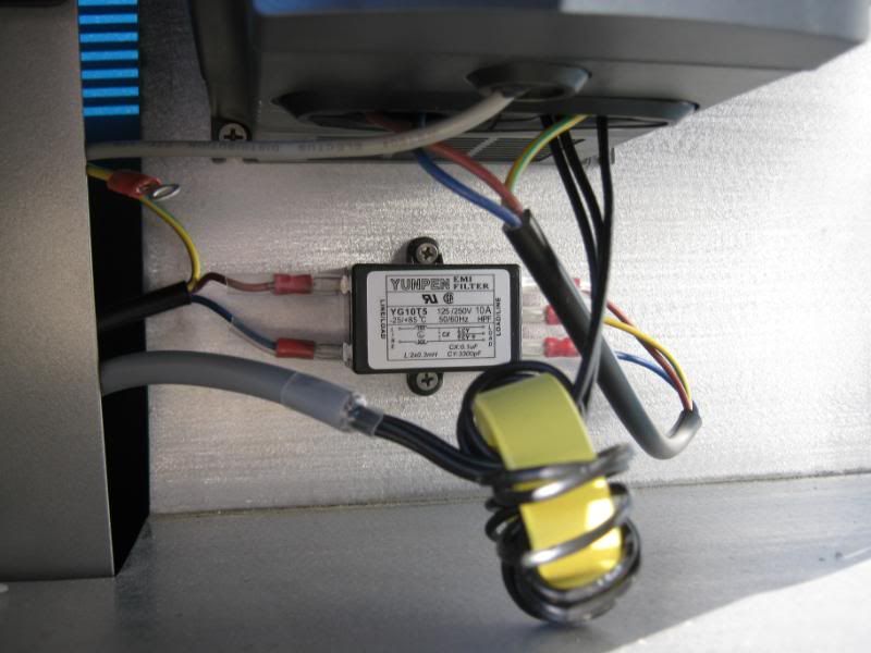 I too will need to check the grounding at the spindle unless Paul can remember?? Looking forward to getting the pluggin working, just got to keep nutting it out!!  Cheers Tony.
|
|
#7
Mon 20 December 2010, 04:56
|
|||
|
|||
|
I tried for 2 weeks to get the Chinese VFD to work but was not successful.
I experienced all the problems you mentioned, I tried a lot of recommendations that I found on a number of forums :-
Nothing worked together, it was either the VFD controlling the motor speed or the PDMX with the Smoothstepper communicating with Mach 3 but not together. In the end I got rid of the VFD and bought a Hitachi SJ200 from driverwareHouse via Woody in the USA. When it arrived I set the parameters of the VFD and everything worked straight away, no problems with EMI, Mach3, BOB or Smoothstepper. Tested across the full rev range. I am very happy with the Hitachi, a professional unit, very well made with excellent English documentation (no translation problems) and backup. There is a whole swag of accessories that can be bought from Hitachi - EMI suppressors, cables, free software to set the parameters of the VFD so you do not have to use the front control panel, braking resistors and reactors for each model of VFD. Have a look at the Hitachi USA web site. The best prices were from driverwareHouse for VFD and accessories. Peter Honmann + others have developed a plugin for Mach3 that will communicate directly (via RS485) with the Hitachi for controlling speed. (Can be downloaded from Mach3 forum) The front panel can be removed from the front of the VFD and be attached to a standard 3m cat5 cable back to the VFD. This is great if you want to mount the VFD in another room away from the dust etc... and still control the VFD beside the computer. The Hitachi uses standard Modbus protocol. Some people have had luck with the Chinese VFD but I was not fortunate to experience this. The Hitachi has worked well with the Chinese motor but time will tell, so far it has had no problems. If you want any further information send me a PM. Cheers Chris
|
|
#8
Mon 20 December 2010, 06:03
|
|||
|
|||
|
danced naked around fire and drank goat's blood on a full moon night- all the usual things to get digital machinery to work!!!!
To each its own cultural ritual .but this must be a real treat to see !!!!  Robert 
|
|
#9
Wed 22 December 2010, 14:27
|
|||
|
|||
|
I have had some requests for the pin configuration of the Hitachi comms cable which I got from Hitachi Germany. I have noticed that this cable is for USB to RS-422 (using a RJ45 plug) not as I thought originally RS-485.
The Hitachi product name is USB-CONVERTERCABLE and it can be bought from Hitachi-america for $120!!! Hope this helps the people who have Hitachi VFDs. Cheers Chris
|
|
#10
Wed 22 December 2010, 14:38
|
|||
|
|||
|
Thanks Chris
|
|
#11
Wed 22 December 2010, 15:05
|
|||
|
|||
|
Greg,
I found the documentation a bit confusing in the Hitachi range. They interchange RS422 and RS485 all through their documentation and sales brochures, I thought they where 2 different standards. Are they interchangeable? Cheers Chris
|
|
#12
Wed 22 December 2010, 15:36
|
|||
|
|||
|
Chris, interchangeable, no. Convertible, yes. Google "RS422 vs RS485" and you'll find info like this that helps to clarify. Both standards only cover the actual wiring characteristics; the serialization of the bits, and the meanings are at a higher level. Generally, though, the grouping of bits into bytes, parity, and the like are standardized at this point (because the same USART hardware to handle this has been in place for decades), so you effectively have a stream of bytes, and the protocol those bytes represents should be in the manufacturers documentation. It doesn't care what type of wiring you're using to send them.
|
|
#13
Wed 22 December 2010, 17:22
|
|||
|
|||
|
Chris
I have all this to learn. Mostly the reason I am having a go at it. Looking quickly at the link Bradm provided (thanks) it looks like RS485 is two wire. This lines up with the info in the Hitachi manual. Peter Homann is very experienced with this stuff. He makes the ModIO boards. And he has a Hitachi VFD. I'm hoping he will set me on the right track when my bits arrive. He lives nearby. It should be much simpler than the Chinese VFDs because it conforms to the Modbus standard. At least that is what I am expecting. We will see. Greg
|
|
#14
Fri 24 December 2010, 04:15
|
|||
|
|||
|
Torroids make a difference
Hi All
One more experiment before Santa arrives!! EMI Test 1.jpeg Originally I just stacked all the 7 barrel torriods I had on the output line to the spindle. As a quick test I moved three of them to the input line and the pluginn worked far more reliably but still not 100 percent. I could reliably start, stop and alter the speed of the spindle EVERY time to 8000 RPM with the three torroids moved to the input side of the VFD. Managing the EMI on the input with torriods was something I had not considered until I read an article on what was actually going on and some of the voltages that were induced were like 10x the input voltage !! A small step in the right direction tonight but as the rain builds here on the East Coast of Australia, some families are going to be wishing Santa bought them a boat. Stay dry you Aussies and stay out of any floodwater. 24 December Sat Image AU.gif Merry Christmas to Everyone. Regards Ross
|
|
#15
Fri 24 December 2010, 17:46
|
|||
|
|||
|
VFD Fix
Hi All
Fixed the Huanyang VFD to use MattyZees pluggin. As we all had pretty much established, EMI was the issue. Today I quickly further experimented with placement of the clip on torriod magnets and my hunch to follow how data cables are sometimes treated for EMI fixed the issue. Note I have attached a torriod to both ends of the RS485 communication cable. Attachment 10906 The spindle control on Mach3 responded perfectly up to 22,00 RPM after tweaking a max spindle speed default in Mach3 that was set to 8,000 RPM. Note at this stage only the PC with the Mach3 controller and the VFD spindle combo are running. A further significant note is that earthing is not yet in place on my machine. It is feasible that anything may happen as additional systems are put in place but it was great to see the spindle and pluggin work together so faultlessly. That would be a very big thanks to MattyZee. Regards Ross
|
|
#16
Tue 28 December 2010, 03:48
|
|||
|
|||
|
VFD Update
I am now getting mixed results once the machine is also brought online.
Generally I feel that having the pluggin in is better than not having it but managing a crash in the communication signal requires intervention beyond just a click or two. Under most circumstances, I simply allow the program to finish then press the stop button on the VFD to stop the spindle. 1. To return control to the Mach3 controller once the comms goes down - unplug the RS485 USB adapter. 2. Once the RS 485 adapter is unplugged the spindle will continue to spin but the G Code program execution can be stopped and started as normal. 3. To return control of the spindle to Mach3 - restart of Mach3. Not a perfect situation but it is controllable, predictable and does not crash all the time in the first place. I will continue to try to improve the performance of the system over time and if I have any substantial improvements I will make sure to put any results in this troubleshooting thread. Regards Ross
|
|
#17
Sat 08 January 2011, 06:42
|
|||
|
|||
|
Hi All,
Still no joy with the Chinese Vfd again today  Thanks to Peter (Tangocharlie) who has loaned me his Hitachi SJ200 to trial, will keep you all posted on the outcome and all going well, we will be ditching the Chinese Vfd's and moving to the Hitachi's. Cheers Tony.
|
|
#18
Fri 14 January 2011, 06:20
|
|||
|
|||
|
VFD Update No2
I have not forgotten this thread but the opto-isolator is still on the way.
Skippy has had some experience with RS-485 (admittedly most of the recent experiences have been bad ) but he mentioned that some cables used a resistor. Hmm we got no resistors only torriods, so a quick read of the sometimes accurate Wikipedia, gave up this information... Ideally, the two ends of the cable will have a termination resistor connected across the two wires. Without termination resistors, reflections of fast driver edges can cause multiple data edges that can cause data corruption. Termination resistors also reduce electrical noise sensitivity due to the lower impedance, and bias resistors (see below) are required. The value of each termination resistor should be equal to the cable impedance (typically, 120 ohms for twisted pairs). The VFD and pluggin work quite well until I use the higher RPM's. 22,000RPM will often lead to a lockup while 15,000 RPM rarely leads to a lock up. It is late here now and even a watercooled spindle at 22K is not overly quiet but I got it to run a few times at very high RPM with the 120 Ohm resistors installed on both ends of the RS485 cable. Will give a real workout tomorrow and report back. At least this is some new information with respect to signal noise on the Huanyang VFD's that has been untested to this point . Cheers Skippy, you know I'm a sucker for an experiment Regards Ross
|
|
#19
Fri 14 January 2011, 16:29
|
|||
|
|||
|
120K Ohm Resistor Test
Ran the spindle at 24K RPM and unfortunately it did not stop on completion of the test Gcode.
It did however stop and start many times during an initial 15 minute period but at some stage after that is must have lost comms. Conclusion I have been unable to establish if the resistors have made any significant difference. Regards Ross
|
|
#20
Sat 15 January 2011, 02:10
|
|||
|
|||
|
10 out of 10 for giving it a go Ross !!
I'm sure your going to beat it !!  Cheers Tony.
|
|
#21
Sat 15 January 2011, 02:52
|
|||
|
|||
|
Read some more - Failed some more
Just in case the 120 Ohm resistor was not correct for the cable I read up some more.
The 120 ohm in the wiki article is an approximation of the characteristic resistance of a typical twisted pair cable. The characteristic resistance spec of a Cat 5 cable is closer 100 ohm. Undaunted I remade a new cable with 100 ohm resistors on both ends, unshielded Cat 5 twisted pair cable (single conductors this time - Cheers Mike) and a clip on torriod on both ends. The earth was also made from the VFD to the GND on the RS485 to USB converter. One run was made with an earth another without. As I have a short cable my instinct is telling me I have a very low resistance in comparison to this type of setup. Full Reference is http://www.maxim-ic.com/app-notes/index.mvp/id/763 Characteristic Resistance.JPG I clearly must have something wrong here - probably the resistance of my cable as I was unable to get a meaningful measurement out of my $20 multimeter !! For all this attention to detail I got my worst ever result. Lost control almost immediately of the spindle even a low RPM. Conclusion The best performing cable was two separate braid shielded cables one for each signal wire. The cable also had some torriods on both ends of the single separate signal wires and the braid shield grounded to the RS 485 to USB adapter. From my experiments, sheilding is the variable that has the most significance upon the improved performance of the RS 485 communications from the Huanyang VFD. Regards Ross
|
|
#22
Sat 15 January 2011, 19:47
|
|||
|
|||
|
Feel Free to Correct My Spelling - Plus one very interesting finding
You all must be so polite - Shielding -not Sheilding.
When I said the RS485 connector was connected to ground - I had actually connected this to the 240 Volt ground on the VFD because I was desperate to get a ground, any ground. I was uncomfortable with this but did it anyway. Overnight I did the very unmanly thing of reading the instructions and found another earth (GND) on the VFD. VFD Terminal Block.JPG ACM Terminal Description.JPG The RS485 Wiring Diagram is something like this. Note the GND wire from end to end. RS485 Wiring with GND.JPG Previously I was only grounding the braided shield back to the RS485 adapter (on one end only). Now as per the schematic, a correct GND connection has been made from the ACM Terminal on the VFD to the GND terminal on the RS485 adapter. I got a couple of good runs at 24K on the spindle but then the dreaded loss of comms was back. This still leaves the terminating resistors as a possible issue as these are designed to suppress noise and preserve the signal. My rough guesses of 120 and 100 Ohms might be doing nothing to reduce the noise as I can not reliably say I have a known cable impedance to work from. Conclusions The ACM to GND connection is a step towards the correct wiring for the RS485 Standard. Definitely don't connect the cable braid shield to the GND wire as well as nothing works at all !! (Could not help myself) Shielding works better than no shielding even with the ground wire in place. Unknowns. Can any one help on the resistor values based upon a 3 meter length of Cat5E twisted pair? Thought Experiment The standard is based on long runs of cable something like 200 feet. We have maybe 10 feet of cable, so the resistance must be far lower. If the resistance of the cable is near zero, then the terminating resistor value should also be near zero. Dangerously I am beginning to wonder if a straight wire between the two might work.Regards Ross
|
|
#23
Sat 15 January 2011, 20:41
|
|||
|
|||
|
Ross, do a quick resistance test with a multimeter, and I think you'll find that all the grounds on that VFD are connected together.
You've been doing a lot of work to try to make the communications link solid in a noisy environment. It might be time to concentrate on making the environment less noisy. Look into what else you can do to choke off noise on the power infeed to the VFD, and on the connection outbound to the spindle. In particular, I'd look into the kind of choke that you can not just pass the wires through, but wrap around a few turns. If you look through the VFD manual of a reputable manufacturer ( for example, the manual of the Hitachi X-200 ), you'll see information on these types of chokes. Finally, don't discount the possibility that the failures you are having aren't due to noise, but due to the software on one end or the other loosing track of the link. Can you slow down the speed you're running the data on that 485 link? Last edited by bradm; Sat 15 January 2011 at 20:50.. Reason: Add reference on type of choke
|
|
#24
Sat 15 January 2011, 22:37
|
|||
|
|||
|
Hi Brad
Thanks very much for the suggestions. With the power off the circuit is open. Not game to do it with the power on. So not quite sure on that one. Baud rate is 9600 so that is very slow - snails could move bits quicker. Software crash - definite possibility. I will download and read the Hitachi x200 manual and do some front end noise control. Skippy went hard on the ring ferrites and got nothing but that is not to say I would not benefit from this configuration. MattyZee's original solution used the ring ferrites. Experimenting without the correct instruments can only get me so far I'm afraid. As I can not see the effect on the signal any measures I have taken directly on an oscilloscope trace like the lovely clear ones above, all my observations just are inferred. Thanks again we will see where I end up on this one after the Hitachi manual gets a good reading. Regards Ross
|
|
#25
Sat 15 January 2011, 22:41
|
|||
|
|||
|
Ross - okay, good that the grounds are actually isolated. I thought I'd recollected I'd seen them tied together at some point. I agree, no need for less than 9600 bps.
Good luck!
|
|
#26
Sun 16 January 2011, 00:46
|
|||
|
|||
|
What helped me when I was having some issues with computer lockup was to disconnect the internal EMC capacitor filter on my Control Techniques VFD, as you see on the picture.
At the time I did not look into it to see where this internal filter is or what it does, but just disabled it. From the picture in manual it looks like it is connected to the braking resistor (which I don't use and it is not connected). I see you tried everything, look in the manual or from others Huanyang for this connection. My symptoms were complete system lockup when running VFD. Here is the picture from my VFD manual: 
|
|
#27
Mon 17 January 2011, 03:39
|
|||
|
|||
|
Lost Control Completely of the VFD
Hi Danilo thanks for your suggestion.
After Brads hint I read the Hitachi VFDd manual and soon became aware of the degree isolation and protection VFD's may potentially need to work. Granted in a not so noisy environment with only one VFD around, shortcuts can be made and they still work well. This evening I replaced the round torriods with ring torriods with 4 windings through each ring. I also made a new comms cable with 68 ohms resistors each end and shielding in place. At this point I went on to try every combination of 1. earthing the shield at one end 2. earthing from the USB converter to the ACM port on the VFD 3. no earthing at all 4. running the PC on a UPS 5. using twisted pair, untwisted pair cables and unshielded cables The RS485 bus would completely loose contact after one motor start each and every time. These changes represent a significant step backwards to the point of it now being unusable. After another flogging at the hands of Huanyang VFD I now admit defeat. Discussion The Huanyang VFD is generally unsuitable for RS485 bus communication. It is however suitable as a manually controlled VFD from the front keypad. I am unable to report reliably on build quality and life span. The cheap fully automated VFD is also a bit of a myth. Before the hate mail starts rolling in let me explain why this is so. Bellow is a section of a schematic from the Hitachi VFD manual. Hitachi VFD.jpg The power train recommended by the manufacturer contains 4 devices before the VFD itself, then a further two devices on the motor side of the VFD. The all up cost of these devices is considerably more than the unit itself. An AC line reactor here in Australia is maybe around $170 and you might be needing two. The other high quality control devices in the manual also looked to be very well made industrial quality products that do not come cheap. As a budget guideline three times the base cost of the VFD is probably a little slim but would do as a guesstimate. Swapping out the Huanyang VFD to another brand VFD brings with it control issues that are not yet documented on this forum. Lets look at my failure as an opportunity to establish a new standard that works for the majority of users. Regards Ross
|
|
#28
Mon 17 January 2011, 06:15
|
|||
|
|||
|
Quote:
|
|
#29
Mon 17 January 2011, 06:49
|
|||
|
|||
|
Picking up on what Gerald mentions, while RS485 may be hard to get working, setting up a quick Optoisolated circuit with a PWM driven Resistor/Capacitor to act as the remote potentiometer is quick and easy, and results in computer control of the VFD speed. I run my X200 this way, no problem (and no additional power conditioning devices or filters).
BTW, the AC line reactor on the input is usually recommended to defend the VFD against variable power due to other devices in the shop (like another VFD on a larger motor, for example). The RF noise filters act to attenuate the noise broadcast by the local VFD as it switches. So the line reactor is for big, "slow" power surges from the source, and the ring toroids are to try to reduce the high frequency PWM noise. It is this latter noise that is most likely to affect communications. While I agree with your conclusions and I really admire the amount of time you were willing to experiment with this, I am suspect of that 68 ohm change. The 120 ohm specification doesn't say "vary this with the length of the wire", so I'm inclined to think that the drivers are designed to work with this magic value.
|
|
#30
Mon 17 January 2011, 07:31
|
|||
|
|||
|
Hi Gerald and Brad
Great ideas there, I was already trying to find out about remote potentiometers. Apparently the knife grinding crew use this solution as well. Brad, for a laugh and to lay blame firmly where it should rightly rest regarding the 68 ohm resistor. Skippy constantly repeated a mantra of "multidrop protocol" and "68 ohm resistor" everytime I spoke to him about this. From my perspective at least, as the topology was point to point, multidrop seemed irrelevant and 68 ohms was plain wrong given what I researched about the protocol. After repeated failure actually using facts to guide me. In a final act of desperation, I took a long, unnecessary, drive to the 68 ohm resistor shop and I listened to him. Go on Skippy defend yourself Regards Ross
|
|
| Register | Options | Profile | Last 1 | 3 | 7 Days | Search | Today's Posts | Mark Forums Read |
| Thread Tools | |
|
|
 Similar Threads
|
||||
| Thread | Thread Starter | Forum | Replies | Last Post |
| Mach 3 CV settings | Greg J | General - MM Operating | 2 | Wed 17 November 2010 14:49 |
| Mach 3 | sailfl | 80. Computer Hardware & Software | 6 | Mon 13 September 2010 13:03 |
| mach 3 setup help | paul60 | 70. Control Systems | 7 | Tue 03 August 2010 11:02 |
| Shopbot VS Mach 3 | Cutter99 | CNC motion control software | 46 | Mon 22 June 2009 04:21 |
| Upgraded Mach, now the motors won't turn - Different ports/pins for later Mach | Hugo Carradini | Troubleshooting | 19 | Thu 25 October 2007 11:45 |


