|
#901
 Wed 11 February 2015, 20:57
|
|||
|
|||
|
Painted. Pictures tomorrow

|
|
#902
Wed 11 February 2015, 23:11
|
|||
|
|||
|
I know, I know..... not telling though

|
|
#903
Thu 12 February 2015, 19:20
|
|||
|
|||
|
New Z axis!
It took a little while to draw this out. I stayed at relatively the same height above the Y car but have some new benefits to the Z. I used a 1610 ball screw with 500mm x 20mm round rails and bearings. I added push adjustments for ease of tramming. I had to make a nylon bushing for the bottom slot so I would have a pivot for front to rear adjustment. There is ±2° adjustment front to rear and ±5° side to side. More than is needed. The steps per inch worked out to 5080 and I can still run 500 IPM rapids. I did gain +2 inches to the retract height. One thing I found before was even though there was 8.79 inches from the collet to the spoilboard, adding a 2.5 inch bit reduced the ability to carve some larger stuff I had to turn away. Now I retract to over 11 inches using the 500mm rails so the bit is up inside the gantry during traverse to the tool change position. I was not looking for this but I worked with the parts purchased. I have full travel to the spoilboard with the collet flat on the spoilboard. Truing the spindle was less than 5 minutes both times. First time when testing and the second after painting. Any questions feel free to ask. Enough already, here are the pictures or click one to see them on Flickr. 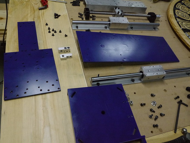 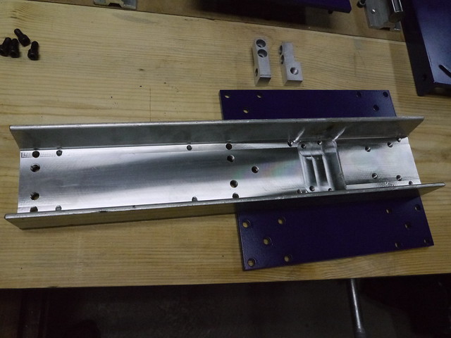 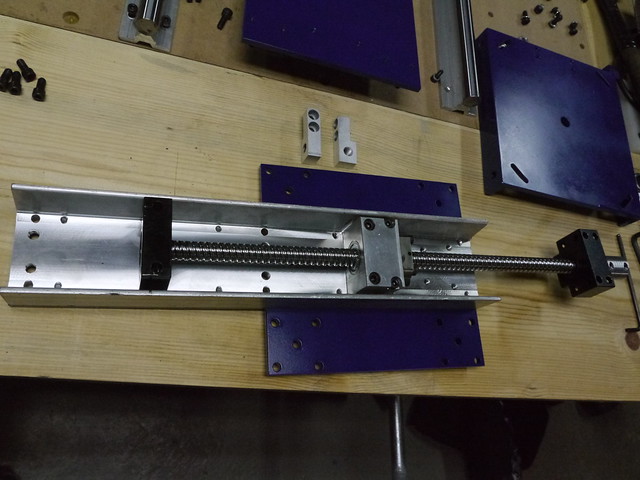 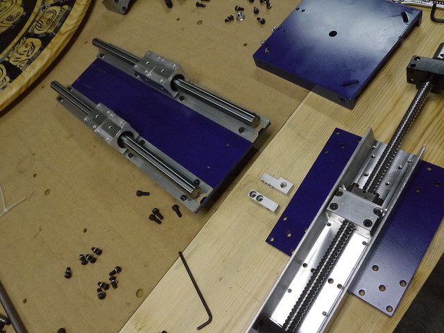 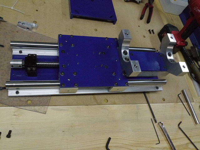  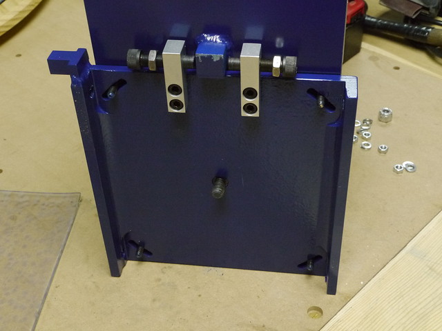 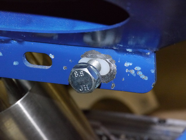  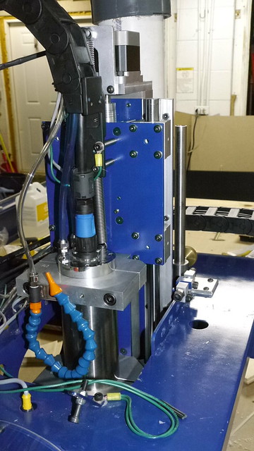
|
|
#904
Thu 12 February 2015, 19:42
|
|||
|
|||
|
Wow, wow, wow! Looks awesome painted Pete, this is definitely on my list of things to do to the MM.
|
|
#905
Thu 12 February 2015, 23:25
|
|||
|
|||
|
Looks fantastic Pete!
I assume you used a section of large channel for the pivot mounting plate? Are all the painted sections steel? Have you tried doing any heavy cutting, how well does the alumimium channel keep the assembly stiff in the forward/back direction? ps - where do we download the cad files???  
|
|
#906
Fri 13 February 2015, 02:35
|
|||
|
|||
|
Looks and sounds good.
A lot of time and effort gone into that. I am sure that it will inspire others. Well done.
|
|
#907
Fri 13 February 2015, 03:31
|
|||
|
|||
|
Pete, nice job. I am interested in hearing about what you have done for the dust collection tube. It looks interesting. Could you post some detailed photos and provide some more detailed info?
Thanks
|
|
#908
Fri 13 February 2015, 04:31
|
|||
|
|||
|
Pete, That is an Excellent Work of Art. I applaud you!
|
|
#909
Fri 13 February 2015, 05:43
|
|||
|
|||
|
Quote:
|
|
#910
Fri 13 February 2015, 05:45
|
|||
|
|||
|
I will provide cad files of the design to anyone interested.
|
|
#911
Fri 13 February 2015, 05:49
|
|||
|
|||
|
Quote:
|
|
#912
Fri 13 February 2015, 05:50
|
|||
|
|||
|
Quote:
|
|
#913
Sat 14 February 2015, 04:59
|
|||
|
|||
|
Very nicly done, inspiring work.
Thks for sharing and your generosity !
|
|
#914
Sat 14 February 2015, 09:39
|
|||
|
|||
|
Excellent work as always Pete!
I really like the adjustments, something I would like to incorporate into my design. As always, thanks for sharing! Mark
|
|
#915
Sat 14 February 2015, 20:20
|
|||
|
|||
|
First cut after upgrade. Cut from a piece of stain grade pine. 12" x 11.25" x 0.75". Model height is 0.74" and is 11" high.
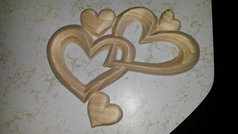 First cut after new z axis, on Flickr First cut after new z axis, on Flickr
|
|
#916
Sat 14 February 2015, 20:23
|
|||
|
|||
|
Sweet...
So, this New-Z seem to work as good if not better !
|
|
#917
Sun 15 February 2015, 02:31
|
|||
|
|||
|
For a moment i thought you had made a double extending z slide...
|
|
#918
Sun 15 February 2015, 19:57
|
|||
|
|||
|
Robert, I may be bias but I honestly think it is better. My touch of probe is slightly off to the spoilboard. This left an onion skin. Before the cut was not as consistent. I was comparing to the Christmas one I cut before. The Z cut appears more even now. There were minute variations before.
|
|
#919
Mon 16 February 2015, 02:54
|
|||
|
|||
|
Hey Pete, may I be the first to request the cad drawings? Thanks.
|
|
#920
Mon 16 February 2015, 03:42
|
|||
|
|||
|
Pete, in my book your not being bias.....it's the being self reward & very satisfied with one own work....and good results
I too tend to believe it may be "better"...... it's nicely thought out, nice materiel, nice build......but...cauz there is a one (but), it's the cost factor. Money can make "mechanical" make things ( among other) go better when those factor are inline. Nicely done mate
|
|
#921
Mon 16 February 2015, 07:09
|
|||
|
|||
|
Tom, do you want the files or the drawings? If files then which format?
|
|
#922
Mon 16 February 2015, 07:24
|
|||
|
|||
|
I'm curious.... may I ask you a DWG ?
In what software did you originally did your drawing ?
|
|
#923
Mon 16 February 2015, 07:26
|
|||
|
|||
|
Rhino 3D
|
|
#924
Mon 16 February 2015, 08:14
|
|||
|
|||
|
I should ask if you can open 3D dwg's or do require 2D?
|
|
#925
Mon 16 February 2015, 10:39
|
|||
|
|||
|
Bookmark to read later...
Cheers, Corei7vne
|
|
#926
Mon 16 February 2015, 13:33
|
|||
|
|||
|
I can open 3d dgw with autocad, but never tried one from Rhino !?
Meaning, it remain an interpretation, not an original dwg from Autocad !!? Let's give it a try, if you do not mind !?...
|
|
#927
Tue 17 February 2015, 01:10
|
|||
|
|||
|
Me too please, 2D - either DXF or DWG
Thanks
|
|
#928
Tue 17 February 2015, 13:15
|
|||
|
|||
|
Me too, please.
Thanks Milosh
|
|
#929
Wed 18 February 2015, 02:49
|
|||
|
|||
|
Thanks Pete.
|
|
#930
Wed 18 February 2015, 17:07
|
|||
|
|||
|
Beautiful work on the Z and the hearts!!
|
 |
|
|
 Similar Threads
|
||||
| Thread | Thread Starter | Forum | Replies | Last Post |
| Parts arrived !!! Time to get to work !! - Pennsylvania USA | Rapid | Introduce yourself and start planning | 51 | Fri 06 June 2014 07:53 |
| Newbe here - Pennsylvania, USA | Dave | Introduce yourself and start planning | 19 | Wed 11 December 2013 17:30 |
| Sign for my self | danilom | The Show Room | 6 | Fri 04 March 2011 04:50 |
| Hot Rod Shop Sign | woody | The Show Room | 4 | Fri 23 April 2010 12:14 |
| Edge lit sign | Jayson | The Show Room | 4 | Fri 20 March 2009 22:55 |


