|
#121
 Mon 25 April 2011, 04:10
|
|||
|
|||
|
Phone rings, Gary asks " Do you know the holes on the gantry tubes are 10mm different at the ends?"
I think, "Must have offset them a bit. My poor workmanship." "Don't worry, Gary, I drilled them off the jig I'm going to use to bolt them on. It won't matter if they are shifted a bit." Pick up gantry. Start to fit rails. Funny, one is 10mm too long at one end. How did that happen. Then I tweaked. Gary had reversed one y-tube - hence the different distances in holes from the ends. Now one y-rail is lighter by the weight of a second set of holes offset from the previous ones by (you guessed it) 10 mm. Moral: have faith in your workmanship. 
|
|
#122
Mon 25 April 2011, 04:34
|
|||
|
|||
|
Rollin' Rollin' Rollin'
We went to "sleep school" with the baby last week because he would rather cry for an hour than sleep for an hour in the day. Spent 5 nights learning sleep technique and training him. Brought him home Friday and he's slept through every night and all his day naps. Now my wife and I have time on our hands again. I can get this machine finished!
Got to love these long Easter weekends. Assembled the gantry rails and removed the x-rails and drilled the holes out and replaced the x-rails and trued them. y-rail with extra holes: 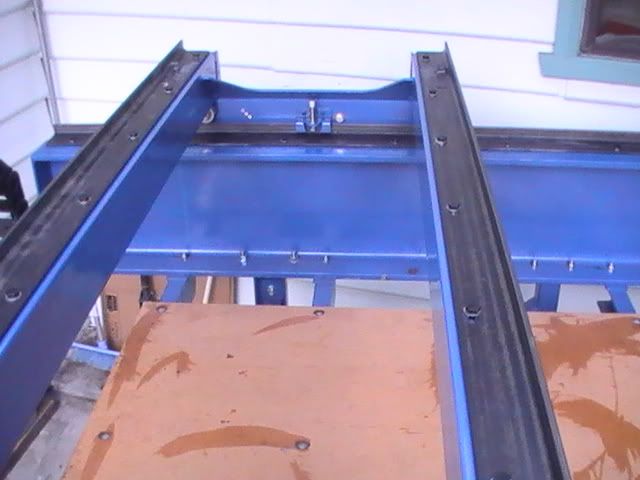 Support board sporting smudges of epoxy from filling the countersink holes. Made some "slippery" (teflon replacement) washers out of a 2mm thick cutting board from my local $2 shop and tried to figure out why I had so many short M12 and M10 bolts in my box. Scratched about in the box to find the fixings to assemble the gantry and y-car. Put the vee-bearings on the gantry and y-car. I used washers as spacers on the gantry and used 2 on one side and 3 on the other (so the gantry is 1mm offset to one side. With the vee bearings off the walls a bit they cleared the bolt head holding the motors on. I did have to reverse the bolts so the nuts were on the outside because the nylock nuts touched the rails. Mounting the motor on the y-car was not as simple because the vee bearings were only spaced one washer away from the walls. I again reversed the bolt so the nuts were on the outside, but the M10 head was too proud and touched the rail. I had to make it a hair thinner. 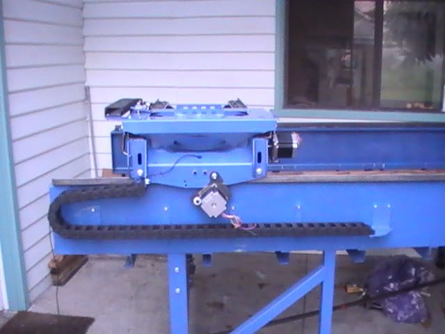 Did some other odds and ends. Cable chains racks and cable chains installed, pinions on motors, bearing on hanger (the bearing shared the oven with the roasting chicken for a few minutes and the support in iced water - just slide together), start on control box (more on that later). Just awaiting double sided tape so I can mount the racks (Darn! Now the 5 day weekend is too long. My tape is in the closed post office until wednesday). Then I can attach the X and Y motors and start pulling wire. 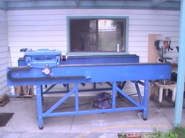 Last edited by Red_boards; Mon 25 April 2011 at 04:46.. Reason: spellign :-)
|
|
#123
Mon 25 April 2011, 05:11
|
|||
|
|||
|
Spider question
I think the last bit of drilling I have to do is to re-drill the 6 holes in the spider.
I had to fill in the first set of holes I drilled and ground the surfaces flat again. This means no markings left. Any smart ideas about how best to ensure I get the 6 holes spaced so the z is centred and actually moves vertically?
|
|
#124
Mon 25 April 2011, 05:45
|
|||
|
|||
|
Red
Looking good. I can't wait until I am up to that stage, but alas the funds will eventually come and I will get there. Keep posting those pics. mick
|
|
#125
Tue 26 April 2011, 01:14
|
|||
|
|||
|
Spider
Red the DXF can be imported into a CAD application to determine the horizontal spacings on the spider.
With respect to getting them vertical - the 4 x M10 bolt holes on the outermost bend in the spider determine the vertical orientation of the spider. These two sets of holes on each side of the spider are your reference back to the holes you need to redrill with respect to the vertical travel. As an example you could place one set of holes against a straight edge and offset by a known distance (say a steel ruler) and just draw a vertical line on the spider. This transfers the alignment of the sides to the flat of the spider. You might also wish to do this on the other side and compare the two lines against each other as the bending may not be perfectly accurate. These transferred lines then give you your frame of reference for marking the other holes out. Another way may be to print the unbent spider DXF and glue it to your bent spider and then punch the marks. This would not be my first choice as it does not give you the chance to correct for any bending error. The final thing you need to establish is the width by using your slide plate and two bearings measured with a vernier gauge. This measurement is specific to your machine as it varies according to the grinding of the slide plate and the fit of the V bearings on that grind. Regards Ross
|
|
#126
Tue 26 April 2011, 13:03
|
|||
|
|||
|
You could print out the spider from the bend drawings and use it 1:1 to line up and then punch the center of the original holes for a guide.

|
|
#127
Tue 26 April 2011, 14:33
|
|||
|
|||
|
Just be careful: computer printers can be off by several per cent, differently in x and y.
|
|
#128
Tue 26 April 2011, 17:49
|
|||
|
|||
|
Thanks.
Ross, nice to see you still check in. Some great suggestions. Simpler than the following approach I was considering. Check tabs still at 90 degrees. Correct if necessary. Measure mid point top and bottom between the tabs. Score mid point line. Use mid point line as reference out to bearings (1/2 x 132mm). One problem with this is parallax errors across the bends.
|
|
#129
Thu 28 April 2011, 22:36
|
|||
|
|||
|
Springs
When I started to assemble I realised that the MM takes 5, not 4 springs (one for each motor and one for the hold down bearing on the gantry). If you got a set off me I owe you one more. If you wanted a set, Apologies, I'm out of springs but can supply the contact.
|
|
#130
Sun 01 May 2011, 19:53
|
|||
|
|||
|
First Roadrunner picture
I couldn't wait any longer!
I got the motors installed, pulled some wire and my electronics engineer wife did the connections. Fired up Mach3 and plugged in the control box panel (sans control box) (the order is Mach3 running, then control power otherwise you blow fuses) and ran the Roadrunner sample file just to see the motors drive the x and y axes. No screams, blood or crashes. I was ecstatic and installed a pen so that I could draw a very small roadrunner on a piece of paper (10x10mm!). Set the steps and scaling and was able to draw a much bigger, reaonably proportioned and recognisable roadrunner. Still several things to do before calling for a number. Most notably installing the Z-axis assembly and completing the control panel case, but also estops, proximity switches, a cutting device (probably a 1550W router I have already). Then some paint touching up and calibrating for sqareness of cut. Then getting the MM's "home" ready (i.e. a level floor, soundproofing and dustproofing an old corrugated garage), plus dust extraction...then a whole lot of figuring out how to actually cut things. Busy month ahead! Overall, though, I (and the rest of my family) am surprised and impressed that it's got this far - and all without too much swearing or blood on the floor. I put it down to great plans and fantastic support. Thanks all.
|
|
#131
Sun 01 May 2011, 23:17
|
|||
|
|||
|
Way to go! I share your excitement, I went buzzard when my MM move on its own for the 1st time.
What is you plan on sound proofing?
|
|
#132
Mon 02 May 2011, 18:01
|
|||
|
|||
|
Hi Ken,
Happy days. Work is back in the way, so progress slows again. I plan on using insulation foam on walls and roof of the shed and working in short spells at reasonable times of the day. It's a hobby machine, so i can get away with this for now, I hope. I'm also cutting foam mostly, so this should mean less noise? Second phase is spindle installation. I'm open to better suggestions.
|
|
#133
Sat 07 May 2011, 04:19
|
|||
|
|||
|
Red - what type of foam are you intending to use?
In the past I have had some experience with sound, so here is a quick summary of what you might wish to look into. 1. ANY gaps in the structure will significantly reduce it's effectiveness - remove all gaps no mater how small (including doors, windows and vents) 2. Concentrate firstly on high frequency attenuation as cutters and routers themselves produce high frequency sound. 3. Low frequency sound attenuation requires mass to be effective, so foams and fibres alone do not have the required mass to dampen low frequency noise. 4. In domestic sound proofing something like densely packed rockwool and thicker 13mm plasterboard as a liner is very effective. 5. Do not confuse insulative value with sound absorption - as more rockwool is packed into the spaces the sound attenuation increases while the insulation value decreases. 6. Mechanical decoupling is a highly effective noise reduction strategy - this includes vibration control and using a room within a room strategy. Lots of pro shaping rooms use the room within a room concept as it provides the mechanical decoupling from the sound source to the receiver. 7. A water cooled spindle will significantly reduce the noise the machine emits, better to use a quieter cutter than try to silence it later. 8. From my limited experience but at least direct experience in cutting foam on a shaping machine, the whole blank sings as the cutter hits it -definitely NOT quiet. 9. Some foams can be a serious fire risk both in terms of fire propagation and toxic fumes when burnt - check up on this point before you go the foam route. Cheers Ross
|
|
#134
Sun 08 May 2011, 04:43
|
|||
|
|||
|
From where I'm from we build everything with bricks... but its going to be a messy job dealing with bricks & mortar. I hope to construct a wood frame based sound barrier which should be faster to implement. Unfortunately, I've no hands on experience on this sort of things... hope to pick some tricks from you guys.
|
|
#135
Sat 28 May 2011, 20:38
|
|||
|
|||
|
I've dry-fitted the Z-axis (no welding of bolts or bearing supports) to check everything fits together. Return motion (i.e. up) of the z is a bit rough. I suspect that the bearings are not exactly in line. Dissemble, check spider is flat, attach bearing supports and sand level.
E-stops are wired in as per http://www.pmdx.com/Doc/AN125-1_MachinePower_02.pdf 1. Trying to figure out proximity switches and pause buttons. According to the PMDX 125 site I can wire the 3 wires of the (10-30V) sensors directly to the BOB without relays. Anyone have experience with this? 2. The pause buttons have got me foxed. I wire them to the unused inputs on the BOB and then tell Mach3 where to expect the signal from?
|
|
#136
Mon 30 May 2011, 05:04
|
|||
|
|||
|
Red
I was waiting for someone else to give you a hand here but it's been a few days so here goes anyway. Limit Switches No experience but I believe that is correct for your model Break Out Board (nice one as it saves on relays). Buttons 1. In Mach3 go - Config, Ports and Pins, Input Signals, OEM Triggers. Set the port number (typically 1 for a single parallel port PC) and the pin number the button is wired to. Step one activates the Pin in Mach3. 2. The trigger logic is either voltage high or voltage low. Set the Active Low column to either a tick or a cross to indicate the logic you have decided to use. Step two sets the pin logic. 3. You have now set up the buttons and their logic BUT Mach3 still needs to know what to do when triggered. So go - Config, System HotKeys Setup, then enter the OEM codes for Cycle start 1000 and Feedhold 1001. Think long and hard about the logic you choose for EACH button independently of what you have chosen for other buttons. You do not want your machine to start if a wire is broken for example, so active low logic for the Cycle Start would be typically not the way to go. A full list of OEM codes is here - http://www.machsupport.com/MachCusto...le=OEM_Buttons Step three tells Mach what to do with the signal. Regards Ross
|
|
#137
Tue 31 May 2011, 20:49
|
|||
|
|||
|
Thanks, Ross.
I had a look at your post on feedhold and cycle start. I see that OEM codes 1001 and 1000 are working for you. These are different from the 1001 and 1005 suggested by Steve Stallings, possibly because of my use of "resume" in my query to him. I don't know what the difference is between the two, but I'd guess that "cycle start" triggers a rewind of code, whereas "resume" does not? I will wire the cycle start active high. I will only have a single resume button (on the control box), so that's a bit less wire I have to pull. My logic is that you may want to stop or pause in a hurry, so buttons to hand on the gantry are useful, but resume might be at leisure, so stepping to the control box is OK (plus it ensures that hands are clear before the dangerous bits start spinning). It seems I have a set of 4 relays looking for a home.
|
|
#138
Tue 31 May 2011, 22:18
|
|||
|
|||
|
Red, the codes are correct as they map exactly to what the Mach3 buttons on your screen say, that is, Cycle Start to Cycle Start and Feedhold to Feedhold.
The cycle start counter intuitively does not rewind the code but resumes from where the Feedhold has been pressed. Mach3 has a separate button specifically to "rewind" the code back to the starting point. You can model this directly in Mach3 without a CNC machine attached, just load some Gcode and press the buttons to see what the tool path does. I do use the Cycle Start buttons on the machine sometimes after pausing to fix or remove a piece of waste, vacuuming etc. Saves some transit time but everyone has their own work method and moving away to restart is good practice from a safety perspective. Maybe just restarting from the Mach3 screen is also a minimalist option you might consider. Regards Ross
|
|
#139
Sun 19 June 2011, 20:48
|
|||
|
|||
|
Hi Ross,
Thanks. I decided to put a cycle start button on my power box, but none on the machine gantry, for the reason you suggest. The gantry carries pause and emergency stop buttons on each side of the machine. Might have to stop in a hurry, but rarely in such a rush to restart.
|
|
#140
Sun 19 June 2011, 22:44
|
|||
|
|||
|
Power Box
The quotes I had for a power box run close to $300. I thought I'd have a go at building one.
I'm an incurable scavenger. I kept my eyes peeled for suitable materials and came up with this: 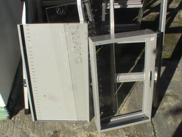 A shelf from a steel cupboard to act as a back A hanging files drawer from a filing cupboard to act as sides - a snug fit width ways in the shelf and just wide enough to take the board I'd mounted on an aluminium sheet. An old perspex sign to act as a lid. It was wide enough to cover the drawer with a few extra mms. Luckily the drawer fitted snugly in the shelf, with some shelf extending at the top (my thinking was that this extra shelf could be used for hanging mounts). After some drilling of holes, a little bolting and judicious use of double sided sealer tape I use for vacuum bags, I've ended up with a passable enclosure. I took the plastic handle out of the ex-drawer "sides" and taped some filter there so there is a place for clean air to enter. Air leaving out of any tiny gaps I missed taping closed should blow dust out (well, here's hoping). Duct tape has been used on the external "wall" face to seal the slots in the shelf and the bolt-heads. I've yet to hinge the perspex lid (may never happen, since the "temporary) duct tape is doing a good job, and intend to make the lid dust proof using duct tape all round (how often do you open the enclosure, anyway?). 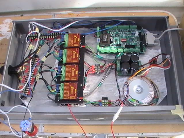 This is a home setup, hence the use of simple transfer connectors over track systems. We've (my wife did most of the wiring) tried to keep high voltage as far from signal wires as possible. The number of loose wires would be reduced with a contacter for the door switches. The wires to the buttons mounted on the "door" have to be long so that the door can open. You can see the emergency button on the open lid at the bottom of the picture. I have yet to decide what to do with the parallel cable. I may install an insulated connector in the wall. Some things I did wrong: 1. I mounted the BOB close to the edge of the base. This has made it very tight for the wires coming into the ports (not far enough from the sides of the box), so I have to remove the BOB to get to the ports. 2. I mounted the board too close to the bottom face, so the wire bundle coming in the bottom does not have space to "spread out" before being attached to the transfer connectors. 3. Because I had the board built before the box, I could not re-drill to reposition components (for fear of aluminium shavings getting where they shouldn't) without dismantling the board. Dismantling gets old pretty quickly. Build the box first. Last edited by Red_boards; Sun 19 June 2011 at 23:03..
|
|
#141
Sun 19 June 2011, 23:13
|
|||
|
|||
|
Love your work!
The box is among the shallowest I've seen so far in this forum. 2 suggestions, you can have the BOB mounted on the box door, either inside or outside of the box (maybe in a separate plastic box which you can screw onto the control box door). BTW, The BOB won't generate much heat, I reckon there are no need to have ventilation for it.
|
|
#142
Mon 20 June 2011, 04:31
|
|||
|
|||
|
Hi Red
Thought the same when I priced the metal electrical enclosures -$300 !! One step closer to a working machine. Regards Ross
|
|
#143
Mon 20 June 2011, 05:38
|
|||
|
|||
|
Call me a fool if you wish, but I honestly can not comprehend how a metal box cost more then 4 stepper motors or a router or a spindle... Its a mystery to me...
|
|
#144
Mon 20 June 2011, 05:45
|
|||
|
|||
|
"Official" electrical enclosures meet government specified standards. Testing and enforcement of standards is expensive, thus the cost of the box greatly exceeds that of the materials used to construct it. That, and as a specialty item, the suppliers keep the prices high.
|
|
#145
Mon 20 June 2011, 06:38
|
|||
|
|||
|
I understand the high price for custom switch box, but these are apparently mass production "standard size" enclosure... The testing can't be as expensive, can they?
|
|
#146
Mon 20 June 2011, 06:45
|
|||
|
|||
|
The size is the problem. The production line, painting, warehousing, transport. And I guess a lot of damage during handling which needs replacements and transport of bulky scrap.
|
|
#147
Mon 20 June 2011, 08:05
|
|||
|
|||
|
That makes sense. Shipping is expensive down-under, that is what preventing me from shipping anything from Australia.
|
|
#148
Mon 20 June 2011, 21:03
|
|||
|
|||
|
I did get a contact who could custom make metal boxes for less, but they were not dust-proof and I'd decided to see what I could cobble together. If I could weld thin plate steel I would have built my own.
|
|
#149
Tue 21 June 2011, 02:44
|
|||
|
|||
|
soldering or brazing are good options too.
|
|
#150
Thu 23 June 2011, 04:57
|
|||
|
|||
|
Mach 3 on Windows 7
After spending a very frustrating afternoon trying to figure out relative home in Mach 3 I discovered that it was Mach 3 confusing me - it would not zero under "machine co-ordinates condition", although the offsets would (sometimes).
Then Mach 3 would not run simple g-code from the MDI input. Restarted Mach 3 and things calmed down. Had to restart on every occurence, though. I looked through the Mach 3 forum and have seen no real resolution. Win 7 (64 bit), Win 7's XP emulator and Win 7 32 bit have all been used with varying levels of success. I was wondering whether there is experience on this forum? PS: is it just my file, or is the neck of the roadrunner.tap not joined between end and start point, and is it very small (I have to use scaling to get it bigger)?
|
 |
|
|
 Similar Threads
|
||||
| Thread | Thread Starter | Forum | Replies | Last Post |
| Making Skins #74 - Brisbane Australia | Surfcnc | MechMates already cutting | 1078 | Sun 20 September 2015 11:05 |
| A chip off the old block | quadtech | Miscellaneous / General / Whatever / Catchall | 0 | Tue 23 August 2011 07:30 |
| Anyone need more bearings? MELBOURNE | rotorzoomer | The Market Place | 1 | Fri 12 February 2010 06:45 |
| M1 18 000 Alternative Stopper Block | dmoore | 20. Gantry | 15 | Fri 13 June 2008 12:47 |
| Rail and Block | John | Archives | 2 | Mon 09 April 2007 15:25 |


