|
#61
 Thu 28 October 2010, 19:00
|
|||
|
|||
|
I hope a forklift is handily by the frame! Great work.

|
|
#62
Thu 28 October 2010, 19:33
|
|||
|
|||
|
Watch out for toes with that guy!
|
|
#63
Thu 28 October 2010, 20:45
|
|||
|
|||
|
Thanks for the encouragement, guys. I need it to keep the motivation going as I move to grinding rails and the trickier welding of Y-car. Wife wants it out of keitchen window and into the "garage" (actually a dirt floor corrugated shed), so it's a weekend of levelling floors and laying forcing mesh and then concreting.
|
|
#64
Fri 12 November 2010, 20:24
|
|||
|
|||
|
Feet arrived
With the Au$ almost at parity with the US$ it makes sense to get stuff from the US at the moment. Mike figured that he could ship 3 sets of feet at similar price to 1 set. I am duly proud owner of 3 sets of feet that arrived well packaged in wrap, foam beads and two boxes with lots of tape! 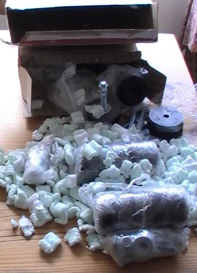 Andrew has already snagged one of the extra sets, so there is another set available to a local builder.
|
|
#65
Fri 12 November 2010, 20:31
|
|||
|
|||
|
Question on Racks and pinions
I know I need to order module 1 racks and I'm better ordering 3m lengths for x-axisif I can. I see that some people have not welded rack segments together, but have simply double taped them in place. How has that worked out?
My main question is on the pinions. The shafts on the motors are 14mm according to my trusty calipers. I can't find a pinion with this size hole (without going to 60 teeth or something). Should I be able to find a ~24 tooth pinion with a 14mm hole or will I have to machine the hole bigger (with all the attendant problems that is likely to bring?) Input much appreciated. Regards, Red
|
|
#66
Sun 14 November 2010, 09:03
|
|||
|
|||
|
Quote:
|
|
#67
Sun 14 November 2010, 16:38
|
|||
|
|||
|
Thanks Gerald.
After extensive search I have found that standard 24 teeth pinions have a 8 or 10mm hold, so I will have to be boring. I see from another thread that Sean has a way of turning a drill press into a lathe for boring out pinions. I also remember surfcnc explained how he did it. Looks as though I might need a few sacrificial pinions.
|
|
#68
Mon 15 November 2010, 01:37
|
|||
|
|||
|
Hi Red
My experiments with the drill press failed. Unfortunately the holes were not concentric. My eventual 'solution" was to be done over by a local engineer to the tune of $160 AUD to put six pinions on his lathe and then tap two M6 holes for the grub screws. After returning them to him to have the tapped holes put in the RIGHT place the second time, he had managed to turn a two day turn around $80 rough estimate job, into a $160, three week long job with errors. If you can find a way of doing them without a lathe can you let me know. Really not ready to subject myself to any more client service like that experience if I can help it !! Regards Ross
|
|
#69
Mon 15 November 2010, 04:24
|
|||
|
|||
|
Ross, your went to a slaugter house???? My friendly neighbourhood machine shop charged me less then a beer for boring, drill & tapping the scrub holes in less then 2 hours... Even after I told him I'm in no hurry to collect them...
|
|
#70
Mon 15 November 2010, 13:54
|
|||
|
|||
|
I had trouble boring concentric holes so I asked my supplier to supply the pinions pre bored to 14mm.
the pinions were 5 pounds sterling each, same bored to 14mm are 17.50 pounds sterling. so basically it'll cost me 62.50 pounds sterling for 5 pinions supplied bored to 14mm. Expensive for 20 minutes work on a lathe but I may pay it for the ease. I'm using the existing non concentric pinions for the moment as I finalise my build and will change to the correct ones once completed. John Last edited by jwt; Mon 15 November 2010 at 13:56..
|
|
#71
Mon 15 November 2010, 16:51
|
|||
|
|||
|
Hey Ross,
It sounds as though the pinions were not the only thing that got reamed! Ken, I'm jealous of you living in the land of cheap services. Here we have OSHA, GST, high rents, minimum wage and all sorts of other costs that get rolled into such services. If I was going to Shanghai again I know I could get it done "round the corner" there for cheap. John, Thanks for the input and benefit of your unfortunate experience. I'm now sure about not spending time with pinions on the drill press. It sounds as though I'm looking for someone who takes beer in exchange for lathe work.
|
|
#72
Mon 15 November 2010, 16:55
|
|||
|
|||
|
Springs
I got a quote for springs today.
4@$15 each 16@$11 each. Contact me if you're local and want to go in on some springs. PS I see Bunnings now has a range of springs, but I couldn't find one close enough to the spec.
|
|
#73
Thu 18 November 2010, 19:39
|
|||
|
|||
|
After a few weeks of doing other things I got to working on the table again. If you recall pictures above I have the leg support substructure resting on top of the upside-down beams. If I were to weld them in place then I could finish the table chop chop. Actually if I had gone for a welded table I could have finished in half the time. Something for bolt togethers to bear in mind.
I've welded tabs onto both ends of the cross supports so that I can locate them in place easier when reassembling the beams i.e. I can get the beams the right distance apart using a mallet so i can locate the bolts (because the beams are resistant to being moved by hand). I've cut and drilled plates and welded them to the table legs and vertical supports. Now to drill the beams so I can bolt the sub structure to them. The Drill Doctor is worth its weight in gold for bit sharpening. So good to see those long curls of steel oozing out of the drilled holes! Anyone have a good tip for locating the centre of a 13mm hole so I can get the holes drilled in the right spot?
|
|
#74
Thu 18 November 2010, 20:42
|
|||
|
|||
|
Red,
Are you referring to the 13mm holes in the rails? If so, you can use a transfer punch (or the 13mm drill bit) to transfer the center and then bore the smaller dia needed. Putting a layer of masking tape on the main beams before you do this step will great aid in seeing the mark you make accurately.
|
|
#75
Thu 18 November 2010, 21:02
|
|||
|
|||
|
We normally use a center punch & make a healthy indent for locating the position & help the drill to stay put at the begining of the drilling exercise.
|
|
#76
Thu 18 November 2010, 22:10
|
|||
|
|||
|
Start by drilling with a bit that is 1/8" or smaller. Using the small bit helps in two ways. A small bit will be easier to keep located on the center punch and having a small hole will help the larger bit stay centered. Always start the bit spinning with little or no pressure when starting to drill. This will keep the bit from biting suddenly and moving off center. After a second or two increase drilling pressure to normal levels.
|
|
#77
Fri 19 November 2010, 00:38
|
|||
|
|||
|
Some pics for you Red
An example of a punch ground down to give a center. IMG_1076.jpeg An example of the hole drilled after the center has been marked. Note rotate the punch and hit it several times to even out any inaccuracy in the conical grind. IMG_1077.jpeg Regards Ross
|
|
#78
Mon 22 November 2010, 05:00
|
|||
|
|||
|
Thanks for all the tips. Here's one in return. Remember these are close to 1/2" holes, so 1/4" punches tend to float around a bit.
I found this epoxy marker pen (with a rattler inside, so it's good quality paint). You push on the felt tip to get the ink to flow. I got a bright yellow one and ran it around the hole followed by a pointed scribe once the ink had dried. This gave a nice outline of the hole. If I did it right the centre of the hole would not be painted. I could then centre punch and use the depression for centering the drill press. Nice thing about using the press is that I didn't have to worry about the drill wandering. Anyway, I'm declaring the table bit done. Now I can hold the beams off the floor and somewhat parallel it's on to thinking about things like rails. The rail grinding plan is to clamp the rails together to give a 190mm wide work surface. Give them a sand to smooth the surface. Clamp the rails to one beam and then attach the grinder and skate top to a 300mm (1ft) wide board and slide this over the beams to cut the rails to height. Probably 1m passes, moving the rail so I'm always cutting using the same piece of beam. Thin blades etc. Comments?
|
|
#79
Mon 22 November 2010, 05:15
|
|||
|
|||
|
You shoul be ok.
As long as you secure the angle rigidly & no large free play between the guide bearing & the work piece. Any inaccuracy can be dealt with during your shimming process. Nice progress. The tough part is almost over.
|
|
#80
Thu 25 November 2010, 01:45
|
|||
|
|||
|
Question on plan M1 20 2220T part
Can the bearing support bases (bushes) on plan M1 20 2220T that are used to space the vee bearings from the spider be replaced with washers as done on M1 20 100?
Much appreciated, Red
|
|
#81
Thu 25 November 2010, 02:26
|
|||
|
|||
|
You are suppose to sand/grind the 4 support bases after they are welded on the spider. This way it takes care of any uneveness on the spider & the possible thermal deformation due to welding.
|
|
#82
Thu 25 November 2010, 04:17
|
|||
|
|||
|
The screws passing through the support bases are only 8mm diam, for which the washers are too small. But, you could jury-rig a stack of "fender" washers, which will probably be too big.
On the gantry & y-car, the 12mm washers are a good outside diameter, and the stack is not as high as that needded on the z-slide.
|
|
#83
Thu 25 November 2010, 13:58
|
|||
|
|||
|
Thanks Gerald.
Too big! Hadn't considered that. Regards Last edited by Red_boards; Thu 25 November 2010 at 13:58.. Reason: fix typos
|
|
#84
Thu 25 November 2010, 18:46
|
|||
|
|||
|
Great progress, I like the table channels. Nothing looks better then solid construction. I remember Gerald telling me to paint the raw pieces first then touch up the finished assembly. Saves hanging upside down like a monkey. I found the Blue finish inspires progress and I need all the inspiration I can get.
I'm looking forward to your updates.
|
|
#85
Fri 26 November 2010, 01:35
|
|||
|
|||
|
Hey thanks Mike (I think)
You gave me a new title: Setting up the spider plate. Is this a subtle way of pushing things along? OK, OK, I'll schedule it in soon. Currently getting to rail grinding, but I like to have a couple things going at once in case it rains or I only have an hour to work. So, yes, I'll get to setting it up :-)
|
|
#86
Fri 26 November 2010, 09:43
|
|||
|
|||
|
I think it might have been due to the discussion of the support bases.

|
|
#87
Sat 04 December 2010, 04:46
|
|||
|
|||
|
Rail cutting
Like many people starting out on their MechMate journey, the thought of making my own rails was the scariest thing. I got to cutting my rails down to 28mm. With some trepidation I set about building a sutting skate and rearranging my beams to create a cutting surface.
I ended up with a rather unattractive assemblage of wood but managed to pilfer handles off two power tools. The handles were invlauable. 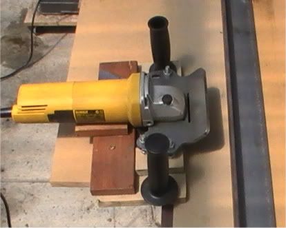 The grinder was marginally different than the skate was designed for so I had to widen the slits in the skate to accomodate the screws. Basically the bolts holding the skate top up are countersunk from the bottom of the supawood base and I used nuts to set the height of the grinder. I was worried about cutting my fingers on the unprotected blade so I added the hardwood spark deflector. I had to remove the grinder to change the thin cutting disks. Since I went through 1 disk/m this was a few changes. Also the height adjustment bolts moved so I had to loctite them in place. Initially I didn't think enough and had the grinder too far from the edge of the base, so I had to cut 10mm off the base so that the disks would still reach the steel when they wore away a bit. I put the rails back to back to form a 180mm wide surface. Since the flanges are not perfectly flat I used a piece of supawood on top of the beams. I clamped the rails to the beams with the wood between. I then has a well supported level surface and could cut away. I would cut through a few inches at the end and then clamp the top strip to the remaining angle so that it wouldn't sag and pinch the cutting blade. I forgot once and ended up with a bit of a wobble in my cut. Luckily it wasn't serious. 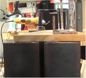 I wasn't delighted with the variation I got in some of the rail heights (maybe partly thin disk bending, partly because the height adjustment nuts shifted during the first couple of disk changes, before I glued the nuts in place), so I clamped the rail pairs back to back, reset the grinder to (28-6mm) and ran a grinding disk over both rails until heights matched. I had to do this on 500mm lengths and clamp the securely to ensure both rails were on the base equally. You'll notice in the pic above that the beams are 10mm or so apart. This is because they (one) are bowed a bit. I assume that I can use welding to pull them into a better line? (otherwise I can't figure how to decide on where to drill the rail holes). The bow is in the direction of the flanges. Do I put some vertical lines of weld on the flat side of the beam? Last edited by Red_boards; Sat 04 December 2010 at 05:12.. Reason: tring to get the darn pic right!
|
|
#88
Sun 05 December 2010, 03:48
|
|||
|
|||
|
Springs
I had a few extra sets of springs made.
Contact me if you're in Australia and want a set for $50.
|
|
#89
Mon 20 December 2010, 17:27
|
|||
|
|||
|
Distractions
Most MM builders have experienced the endless list of distractions that occur during the process of building the machine.
My latest one is rather welcome. I'm training him to sleep through the gentle sound of metal grinding and cutting.  Last edited by Red_boards; Mon 20 December 2010 at 17:29.. Reason: reduce picture size
|
|
#90
Mon 20 December 2010, 18:53
|
|||
|
|||
|
Congratulations Red! Truly an amazing event! When I had my son almost 9 years ago, I was doing a whole house renovation. I worked countless nights with saws and shop vacs and all sorts of noise going on. The boy learned to sleep though it all. The only problem now is he will still sleep through almost anything.
|
 |
| Register | Options | Profile | Last 1 | 3 | 7 Days | Search | Today's Posts | Mark Forums Read |
| Thread Tools | |
|
|
 Similar Threads
|
||||
| Thread | Thread Starter | Forum | Replies | Last Post |
| Making Skins #74 - Brisbane Australia | Surfcnc | MechMates already cutting | 1078 | Sun 20 September 2015 11:05 |
| A chip off the old block | quadtech | Miscellaneous / General / Whatever / Catchall | 0 | Tue 23 August 2011 07:30 |
| Anyone need more bearings? MELBOURNE | rotorzoomer | The Market Place | 1 | Fri 12 February 2010 06:45 |
| M1 18 000 Alternative Stopper Block | dmoore | 20. Gantry | 15 | Fri 13 June 2008 12:47 |
| Rail and Block | John | Archives | 2 | Mon 09 April 2007 15:25 |


