|
#31
 Sun 03 February 2008, 11:17
|
|||
|
|||
|
Thanks for the offer Doug.
Here is the spec on a typical $20 proxy from automation direct: 10 to 30V DC, can take 100mA load. . . . Now to find a common relay, 12V coil, drawing under 100ma. Relay coils often rated in Watts - we want under 1.2 Watt (1200mW). I don't think the relay speed is important, but gold contacts would be nice for the low voltages of the parallel port. 
|
|
#32
Sun 03 February 2008, 12:05
|
|||
|
|||
|
. . . . and then thinking of the low contact voltages makes me doubt the use of relays all over again

|
|
#33
Sun 03 February 2008, 12:23
|
|||
|
|||
|
Sounds like you need a low signal PCB mount.
Have a look at some of these, alternatively reed relays would also suit your needs: http://www.mouser.com/catalog/633/1609.pdf. Mouser is a good supplier in the states, but these type of relays are readily available through any reasonable electronics supply company worldwide.
|
|
#34
Sun 03 February 2008, 12:54
|
|||
|
|||
|
Thanks Bernard! That V23079A1003B301 looks good. The fact that it has the lowest price ($1.84) probably means it is the most popular. (Other options on futher pages all look okay - prices rather similar)
(It is available here in S.Africa from a RS Components at an equivalent price of $6 each)
|
|
#35
Sun 03 February 2008, 15:37
|
|||
|
|||
|
Gerald, are limit switches and proximity switches used for the same thing? (eg: homing and setting limit stops) I have been reading a lot lately about each type with variations within each type. It is all a bit confusing for the electronically challenged. I see from pics on JR's personal page that he has used a limit switch (I think that is a limit switch then again it might be a proximity switch). Now there is talk of low voltage relays etc.
Very confusing. Paul
|
|
#36
Sun 03 February 2008, 22:16
|
|||
|
|||
|
Sorry for the confusion Paul. Yes, they are used for the same thing. JR is using "limit" switches, they are not "proximity" switches
A limit switch contains a mechanical switch with contacts that physically open and close to make/break the circuit to the BOB. The BOB only draws a tiny current at a low voltage, so we must be sure that these contacts stay very clean. Gold-plated contacts prevent them from tarnishing. A proximity switch has no moving parts. It has a transistor based output which is tricky to match correctly to the BOB. The talk of relays in this thread is to add a relay to each proxy, so that the proxy behaves like a classic "limit" switch. Then, why not use a limit switch instead of a proxy right from the start? The proxy can look at the rail all the time, the limit switch can only see lumps at the ends. The limit switch might see a wood chip as the end of the rail, the proxy won't make that mistake. A limit switch won't know if a car has jumped off the rail, the proxy will shut everything down when a car jumps. Proxies are standard on ShopBots and some other CNC machines I believe. We havn't got them neatly figured out for a MM yet. Limit switches are easy to figure out and they are also common on CNC machines, but they are known to be troublesome at low voltages/low currents if the wrong type is selected.
|
|
#37
Mon 04 February 2008, 00:41
|
|||
|
|||
|
Thanks for the reply, Gerald. You made it quite clear. I am a long way from any switches so I will wait to for you and the others to figure out the proximity switch option, that sounds like the better choice. This forum is a great resource when one doesn't quite understand how something works. I appreciate it when I can benefit from someone else's experience. I hope that I might be able to contribute something that would help others.
Thanks again Paul
|
|
#38
Mon 04 February 2008, 10:01
|
|||
|
|||
|
Here is a simple schematic that shows how NPN N/O type proximity sensors could be interfaced to a break-out-board. I used Balluff BES M12MI-NSC40B-SG4G sensors, which are NPN (sinking), Normally Open. Those sensors can use any DC voltage from 12V to 24V. I use 12V.
Basically, here's how the circuit works: 12VDC is applied to the circuit through a 1A fuse. D1 is an L.E.D. to show that voltage is present. R1 limits the current through the L.E.D. to about 10mA. C1 is a filter capacitor. U1 - U4 are the proximity sensors. U5 - U8 are opto-couplers. R3 - R6 are current limiting resistors to limit the current flowing through the opto-couplers' diode to about 10mA. R7 - R10 are pull-up resistors to hold an inactive signal to about 5V (High). U9 is a 7408 AND chip. As long as all of the proximity switches are OFF (not sensing a target), the output (pin 8) will be HIGH. If one or more of the proximity sensors is ON (sensing a target), the output will be LOW. C3 is a small decoupling capacitor that should be placed near pins 1 and 14 on U9. The 5VDC circuit has a fuse, L.E.D., resistor (330 ohm) and capacitor, that function similar to those components for the 12VDC circuit. The Ground lines are common and should be connected together. From an e-mail by Mike: I did a quick dirty board layout that I'm sending to you along with the schematic. Feel free to give it to anyone who wants to have ExpressPCB make three prototype boards. That service costs about $60 here in the U.S.A. At any rate, anyone can play with the schematic and the layout to make it do whatever is necessary. The software is free from www.expresspcb.com. (Of course it is only usable with ExpressPCB's service.) To make the parts fit the quick-turn board (3.8 X 2.5 inches), I had to leave off the fuses. The screw-terminals that fit the board are Phoenix Contact MKDS1,5/3. One point of possible error is that I'm using NPN Normally Open sensors. For this circuit to work, the circuit goes active whenever any ONE of the sensors senses its target. Last edited by Richards; Mon 04 February 2008 at 10:06..
|
|
#39
Mon 04 February 2008, 11:07
|
|||
|
|||
|
Looks more "professional" than a row of relays! What about some visible LED's to see which proxy has lost its target (the proxy's themselves have LED's but they are buried in the beast)?
Volunteers to make up a board & kits? 
|
|
#40
Mon 04 February 2008, 15:00
|
|||
|
|||
|
I don't mind attempting to build this system and using my machine as a test bed but I'm not sure anyone would want a kit I made if it included electronics.

|
|
#41
Mon 04 February 2008, 18:09
|
|||
|
|||
|
One of my daughters is dating an electrical engineering major so I'll see if he can come up with a circuit board printout I can etch and drill. Mr. Richards, do you have a source from which you would recommend I order these parts?
|
|
#42
Mon 04 February 2008, 18:49
|
|||
|
|||
|
Mr. Richards,
Is it possible that the part number on that proxy is BALLUFF ES-M12EL-NSC40B-S04G rather than SG4G? I couldn't find SG4G sensors.
|
|
#43
Mon 04 February 2008, 19:46
|
|||
|
|||
|
Doug,
I just cross-checked the Balluff catalog (sensor catalog '05). The NPN sensor that I use is found on page 1.32 and has the part number BES M12MI-NSC40B-. The suffix, S04G is only found on the plastic parts bag. That suffix might be the quick-connector number that mates with this particular sensor. I bought two more sensors and some more cables from Fiero Fluid Power. The sensors cost $55 each and the cables are about $14 each, depending on the length. Today they only had 7.5m cables in stock. I'm sending a schematic with board layout to Gerald. Everything was done using ExpressPCB, which is a company that provides quick turnaround circuit board manufacturing. They also give away their software to make designing simple circuit boards fairly easy. Their fastest prototype service costs about $60, which includes three 2-sided boards (without silk-screen or solder-mask). The only drawback is the board size for that service, 3.8 X 2.5 inches. This particular design just barely fit that layout. That same board with silk-screen and solder-mask costs about $11.50 each when thirty boards are ordered.
|
|
#44
Mon 04 February 2008, 20:06
|
|||
|
|||
|
This PC board kept me awake last night.....it needs to be thought through a bit more:
- Location of board. To minimise wiring/cabling, this board should be riding the gantry or the y-car. Proxy's typically have 2 meter [6ft] leads - if all 4 proxy's have to reach the board without extensions then the location could be immediately after the y-chain. - Housing. Since the board will not be in the control box, a housing needs to be selected and the board sized accordingly. - Gantry autosquare. The 4th proxy for the slaved gantry motor needs to go independently to the BOB if autosquaring is desired. Maybe a jumper option to have 4th proxy in series or independent? - Z-zero. Many folk will be using a touch plate to zero the cutter height to the workpiece or the table. This can be in the same series circuit as the other switches, but the logic is reversed (contact is made instead of broken). Can terminals and chips be put on this board to connect the z-zero wires and reverse the logic? - Junction central. Since we have already established this board is riding the car, in a housing, gathering all the proxy leads together (+z-zero) and has cabling to the PMDX, it might be useful that this board be expanded with more terminals to break out to all the pushbuttons (low-voltage) on the gantry. In effect, have this board extend the BOB all the way to the gantry . . . . . Food for thought
|
|
#45
Tue 05 February 2008, 06:36
|
|||
|
|||
|
Mike, Thanks for pointing me to the source and for designing this circuit and board layout.
Gerald, I don't know what I was thinking when I wrote my post last night. I can put together kits containing loose parts and ship to MM builders for my cost. With all of the help I've received during my build, this is my chance to pay something back. I was thinking about the PC board too. It occurred to me that I might be able to use the MM to mill the cladding off if the components aren't crammed on there too closely. At least for the prototype anyway.
|
|
#46
Tue 05 February 2008, 06:39
|
|||
|
|||
|
Gerald,
Normally, I build everything around a little 20-pin microcontroller so that features can be added with software - instead of a hardware redesign. The limitation of using a microcontroller is that most of them require a special programmer to write the program into the chip. The programmer that I use is fairly basic in operation, but it still costs about $1,000. It's had plenty of use on lot's of projects, but it isn't something that everybody would want to have on hand. When this discussion first started, I thought about building a 'proper' auxiliary controller with 22mm bypass switches for each proximity sensor, 22mm indicator lamps to show the status of each sensor and as many other 'features' as the 20-pin microcontroller would allow, but just the 22mm parts and pieces for that device would cost well over $100. However, if you can come up with a useful design that can be implemented with a microcontroller, I'll be happy to program chips for anyone who doesn't have access to a programmingr device. Last edited by Richards; Tue 05 February 2008 at 08:05..
|
|
#47
Tue 05 February 2008, 07:15
|
|||
|
|||
|
Mike and Gerald,
I have access to a programming device as well if anyone needs devices programmed. Or even for board building, for the soldering challenged.
|
|
#48
Tue 05 February 2008, 08:35
|
|||
|
|||
|
For those that havn't noticed it yet, more has been added to Mike's post with the schematic (post #37)
Mike, the programmed microcontroller approach is probably the most elegant. It would put those of us in Africa, India, etc. out of the loop for "upgrades" which are likely to be numerous in the beginning. But I have enough patience to hold back on getting the first few versions. My approach to these things is from a hardware perspective, as you might have noticed above; It must fit in a box that rides the gantry. Leading into that box: 1 cable via the chains to the PMDX inside the control box 4 cables out to proxies 3 cables (one each) to the three pushbutton stations 1 pair of connection points for a touch plate (normally open) 1 pair of connection points for a touch probe (normally closed) *new requirement
|
|
#49
Tue 05 February 2008, 19:11
|
|||
|
|||
|
Relays for limit switches
A little something I found at Winford.com. An electronics supplier I use often for small break out relay boards and isolation contacts.
The board is available with three different relay coil voltages (5, 12, 24 VDC), allowing you to choose whichever is most convenient for your project. Please note that the relay coil voltage you select has no effect whatsoever on the voltages you can switch with the relay contacts. For mounting on a panel, we suggest the rubber feet version (-FT), 1/4" nylon standoffs under the mounting holes, and #6 screws. For more information, please see:Features
These products are also available with DIN rail mounting clips for quick and convenient mounting where DIN rail is used. Product numbers ending with -DIN come with DIN clips already installed and ready to mount. The clips allow mounting on standard 35mm rail as well as 32mm rail. 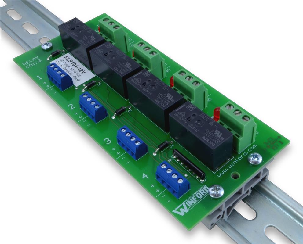 (RLP104-12V-DIN pictured - rail not included)
|
|
#50
Tue 05 February 2008, 22:15
|
|||
|
|||
|
Sean for that application I prefer to use this style:
Only 6mm per relay, DIN rail mountable, any quantity and the relays are plug-in replaceable without fiddling with wires. I think there is version of this that is friendly to proxy's ("busbars" running through) but havn't been able to locate them. I seem to recall they were made by Phoenix?
|
|
#51
Wed 06 February 2008, 10:40
|
|||
|
|||
|
Gerald,
Funny you looked that one up! I use them regularly from FactoryMation. Exceptionally small form factor and they have both NC and NO contacts. Plus, 3 voltages to choose from 12vdc, 24v ac/dc, 110v ac/dc. The PC board in the previous post was for discussion/reference only for those interested in making a board of their own. Not for me...I like machine automation gear - easier to replace. Bus bars are available for these relays. If you look at the accessories page associated with this relay, you will see they sell them in 20 & 30 connection lengths...cut to fit. Three colors available. Last edited by smreish; Wed 06 February 2008 at 10:42..
|
|
#52
Wed 06 February 2008, 12:31
|
|||
|
|||
|
Gerald,
What you've described should be fairly simple to construct, but, we'll need some more information. PMDX: How many signals to the PMDX and what polarity (active High or active Low)? (I'm assuming three signals; one from the proximity switches and two from the touch plate - one active high and one active low.) Proximity switches: NPN or PNP? Normally Open or Normally Closed? (I use NPN, Normally Open) Pushbutton Stations: Are all three pushbutton stations linked serially? What do you want this auxiliary box to do when a pushbutton on one of the pushbutton stations is pressed? Touch Plate: Normally open contact: Is this contact Active Low (input always sees +5V until the cutter touches the plate)? Normally closed contact: Is this contact Active High (input is at ground potential until the cutter touches the plate)? Voltages: +5V +12V Common Ground (Voltages supplied from the control box via the PMDX cable?) L.E.D.s: +5V present +12V present One L.E.D. for each proximity switch? One L.E.D. for touch plate N/O One L.E.D. for touch plate N/C Bypass Switches: Do you want switches to bypass each proximity switch?
|
|
#53
Thu 07 February 2008, 09:32
|
|||
|
|||
|
Mike, I am not ignoring you, just giving all of this careful thought. . . . . . .
Would love some other folk to chip in with wish lists as well. In my mind's eye I see it as a way of bringing the PMDX-122 (at least a large part of it) all the way to the gantry. The part of the PMDX that stays in the control box "drives" (geckos and relays for dust collectors, etc) - the part out on the gantry "receives" (limits, homes, p/buttons, touch plate, probe) Out on the gantry we have lots of wires to be terminated and held securely.....I see mostly a lot of stupid terminals and relatively little board space with smart chips on it ....... Anybody else?
|
|
#54
Thu 07 February 2008, 10:46
|
|||
|
|||
|
As long as we get proximity switches, I'll be a happy camper. I'd love to add the laser pointer but I don't know that we necessarily need it to be connected to the PMDX. Might be nice to turn on and off with a pendant so I guess a connection to the PMDX would help in that regard.
|
|
#55
Thu 07 February 2008, 10:58
|
|||
|
|||
|
I posted a while back but cant remember which thread about a company on ebay that was selling boards that worked in conjunction with the bob to enable connections for limit switches and e stop functions but nobody ever weighed in with their opinions on it.
|
|
#56
Thu 07 February 2008, 11:01
|
|||
|
|||
|
Craig
Here it is: I'm not sure if this is the right place for this or not but I have been watching a sellers store on ebay, http://stores.ebay.com/HUBBARD-CNC-INC he has limit switches for sale cheap but the things I really wanted to were the power supplies he has and he has (for lack of better terminology on my part) a pass thru db25 connector that is supposed to protect your computer and it breaks out the e stop and limit switches all in one. It has USB connectivity on one of the models. If I understand it right it goes between the pmdx and the computer so does it give the ability to ouput mach to the controller via usb and does it make it easier to set up e stops and limit/homing switches? again this loosly fits this thread but feel free to move it and if anybody with more knowledge about this would look and give their input I would apprieciate it. You just needed to do a search on your name.
|
|
#57
Thu 07 February 2008, 11:54
|
|||
|
|||
|
yes thankyou, thats the post, he however has other boards besides that one that I was refering to that handle limits and estops maybe something to look into but as I am the least informed I just wanted to point a direction.
|
|
#58
Thu 07 February 2008, 17:02
|
|||
|
|||
|
Quote:
With the simple touch plate that I advocate, the second option is not so desirable. It implies to me that the tool is at 5v. This may come into conflict with normal machine grounding. Greg EDIT: I see on more careful reading that this was not what Gerald originally suggested "1 pair of connection points for a touch plate (normally open)" "1 pair of connection points for a touch probe (normally closed)" Probe not Plate. Last edited by Greolt; Thu 07 February 2008 at 17:12..
|
|
#59
Sun 17 February 2008, 20:35
|
|||
|
|||
|
Here is my proposed proximity homing/limit switch layout w/ relays.
Prox switches rated at 10-30VDC...I am supplying 12Vdc from output on Antek transformer. I ordered 5v, 12v and 56v outputs on my transformer. Based on the wiring logic supplied by factorymation pdf...I believe I have this correct. Any takers to verify my schematic? Sean prox_layout.pdf
|
|
#60
Sun 17 February 2008, 22:09
|
|||
|
|||
|
Your schematic shows +12 and -12V, therefore 24V relay coils. Was that your intention?
|
 |
| Register | Options | Profile | Last 1 | 3 | 7 Days | Search | Today's Posts | Mark Forums Read |
| Thread Tools | |
|
|


 RLP104 Datasheet


