|
#361
 Wed 15 September 2010, 08:31
|
|||
|
|||
|
Chopper,
Thanks for your suggestion.I have the heavy gantry but I am not sure which choice is better than between type XL and type AT5. Anyone can give the advice to me with the more information. What is the advantage and disadvantage of type XL and type AT5 ? Mongkol 
|
|
#362
Wed 15 September 2010, 09:25
|
|||
|
|||
|
Ton,
do you have a link to the t5 belts and pulleys? or specs on them, or show me a web site that has them and then we could compare the specs and see, //chopper
|
|
#363
Wed 15 September 2010, 09:29
|
|||
|
|||
|
Chopper,
You can see what is different from this link.---> http://www.econobelt.com/e-store/Pulleys.htm Ton
|
|
#364
Wed 15 September 2010, 16:06
|
|||
|
|||
|
Hi TON. I am choppers brother and know his machine well. Chopper is out of town for the day so he cannot reply. I looked up the specs on the t5 belts and they are rated at 457lbsf per inch. The belts we use are kevlar reinforced and are rated at 130 lbsf per 1/8 inch of width. !30 X 8 = 1040 lbsf per inch. So these XL belts are rated at more than twice the capacity of the t5 belts.
|
|
#365
Wed 15 September 2010, 17:05
|
|||
|
|||
|
Hi Ton
Your question sparked my interest. First up the fundamental difference (as we all know) is size. So what seems to be happening is people with a metric system use metric pulleys like the T or AT size and people using an imperial system use the XL size pulleys - an imperial size pulley. It seems the only real benefit of using a metric or imperial pulley type over another is when you are copying a design directly your copy "just fits". The real difference is a little more interesting as these two graphs explain for two metric pulley types. AT5.JPG T5.JPG So my best guess is that the different types of pulleys have a different power distribution curve. Without doing your sums directly for you the two important variables seem to be ... 1. Will it fit your belt drive design 2. Does the pulley and belt handle the power you intend to put through it in your RPM range. Regards Ross
|
|
#366
Thu 16 September 2010, 12:21
|
|||
|
|||
|
Ton,
I had a big long response typed out for you... with a kinds of data and facts and figures, but then I realized that to an extent it really doesn't matter, the XL with Kevlar are stronger and have a breaking point of 74,880 oz inches, the at5 belts @ 10mm has a breaking point of 34,571. oz inches, the work load on the at5's are 25,947.264 oz inches I do not know what work load is on the xl's but I am sure it is higher than the at5's and if you use 860 oz inch motors with a 4 to1 reduction that would put you at around 3440 oz inches at the final drive depending on which pinion you use... so you see that the breaking point is way higher on both type belts than what you will need, since you are not pushing a bit through some kind of material you will not have much of a load on any drive on the machine... this is where practicality and price come into play, which is easier for you to get? which one costs less? is there a big difference in price? if not I would opt for the strongest one (more bang for the buck) also if you go with smaller motors with less rotating mass (inertia) you would gain a faster machine with better cornering (ramping because of inertia ) I Am using 450 oz inch motors on my machine and I would have used smaller ones if I could find them.. //chopper Last edited by chopper; Thu 16 September 2010 at 12:38..
|
|
#367
Fri 17 September 2010, 02:02
|
|||
|
|||
|
All,
Here's the added information . The XL is the USA trapezoidal profile standard. The AT5 is the European trapezoidal standard in which the AT stands for antibacklash. Chopper, It seems the XL type can get the work load better than the AT5 type. I am little puzzled .I don't know why AT type is more expensive than XL type with the same teeth. Normally, I see the most of CNC people use XL type,not AT5 type. Rascle, Ross, Thank for your information as well.
|
|
#368
Fri 17 September 2010, 07:30
|
|||
|
|||
|
Ton,
hope the info helped you, I am looking forward to seeing pictures of your build... good luck. //chopper
|
|
#369
Sat 18 September 2010, 23:43
|
|||
|
|||
|
Quote:
For belts manufactured in same materiales (according to econobelt information), a 10mm AT5 belt will carry 343lbf/in*0,394in = 135,142lbf; a 3/8" XL belt will carry 343lbf/in*0,375in = 128,625Lbf; AT belt is slightly better than XL belt, and remember, AT profile is specially designed for linear positioning and control motion. Ton, AT5 belts are not equivalent to XL belts in profile terms, AT5 profile is specially developed for linear position and motion control. Standar belt profile in Europe is T belt, is the closest equivalent to XL profile. Both belt profiles (T & XL) are designed for conveying applications. A kevlar reinforced 10mm AT5 belt will be better than a kevlar reinforced 3/8" XL belt, but the price will be higer because is a special profile belt. People use Xl belts instead of AT5 belts because XL belts they are most common. There are more specialized belt profiles, like STD5, HTD5, etc, but they are expesive and rare to find, but better in performance terms. Regards
|
|
#370
Sun 19 September 2010, 10:42
|
|||
|
|||
|
Edgar,
I was using the info provided to me I do not know if the materials were the same, if I was wrong I stand corrected, but my point was either belt would do the job, if the at5 has a Kevlar reinforced belt I did not see it.... thanks for the correction ... //chopper
|
|
#371
Sun 19 September 2010, 11:18
|
|||
|
|||
|
Edgar,
I went back and looked up the info for the XL belts with Kevlar reinforcement, and it says that they are rated for 130 ft lbs. per 1/8 of belt width, which puts the breaking strength at 390 ft-lbs. so I guess you are not looking at the belts with Kevlar, which are stronger than the AT5 belts, unless they have a kevlar version also which I did not find....but the point is still that either one will work. and that is all that I was saying.... //chopper
|
|
#372
Wed 22 September 2010, 08:56
|
|||
|
|||
|
Quote:
Regards
|
|
#373
Wed 22 September 2010, 19:04
|
|||
|
|||
|
Edgar,
I see your point, I do not know what the design differences are between the two systems, all I know is that the XL's that I am running work great, on all the machines that my drives are on, but that does not make them better than the at5's, if the AT5's perform better I would truly be impressed, since the XL's perform so well.....it will be interesting to see how they perform when someone puts them on their machine, there is also the cost, Ton said that the AT5's cost more. I don't know if it is enough to be a factor or not...thanks Edgar for the clarification. //chopper
|
|
#374
Thu 23 September 2010, 15:46
|
|||
|
|||
|
I caved in and purchased the 10:1 gear reduction boxes. If i had a working CNC machine i would have made my own, but i dont currently. They are very High quality and are amazing.
I'm using large servos that output 3200RPM, not steppers. I'm using the gear reduction to reduce my speed into usuable IPM. A 10:1 will net me 1056 IPM can you imagine using a 3:1 or 4:1..? haha totally unusable speed. For steppers thats fine, but not for my application. I built the mockup out of MDF to test fit everything. Using a 18lb spring. Final version will be made out of 1/2" Aluminum plate. If anyone can take the time to take a peak at my Youtube videos, as well as a few pictures or my forum thread it would be truly appreciated. Build Log: http://cnczone.com/forums/showthread.php?t=103291 Videos: http://www.youtube.com/watch?v=gat5VTwg-b8 http://www.youtube.com/watch?v=wVH7ew0KEBI My only question is: What angle is best for the servo to intercept the rack with the pinion? 45 degrees? In my solidworks rendering i have a max travel from parrallel- 60 degrees. I was thinking 45 degrees might be best, but i dont know if that really matters? I can move the rack anywhere i really want, its not fixed yet so i can do 0-60 degrees. Please someone let me know so i can adjust my design accordingly. Is a 18lb spring enough? See any other issues? Thank you everyone. *edit:6arc minutes backlash on a 1" spur gear is only .0008"* =) I can live with that.
|
|
#375
Thu 23 September 2010, 18:52
|
|||
|
|||
|
Correction above: I have 0-45 degrees of freedom. The previous cad model is @ 45 degrees, the mock up model WAS positioned @ 10 Degrees. The attached picture to this post is now angled at a 45 degree intersection (pinion to rack). What is the best approach. I want to get this figured out and buttoned up tonight so i can move forward. Is 10 to little and 45 to much? As long as there is the spring force on it what does the angle actually have to do with?
Thanks everyone!
|
|
#376
Thu 23 September 2010, 19:02
|
|||
|
|||
|
Very interesting design. I have a question for you.
What will keep the rack from being shoved away from the Z car? I was thinking a bearing riding on the back side of the rack may be better than pushing on the z car. kenneth
|
|
#377
Thu 23 September 2010, 20:22
|
|||
|
|||
|
The rack is just sitting there for now. Im going to use 1"x1" aluminum 6061-T6 Angle .125 wall backed up against the rack. Its going to be drilled and tapped to the rack, and i will probably use 3M tape on the bottom of the rack just for added strength.
The rack is the easiet part. The machine had a 95" precision ground ball screw that went south and was to much money to rebuild. It was a custom ballscrew and nut which they do not make a over the counter product that will fit its original mounting specifications. It had such a high pitch on it im glad im going this route instead.  Anyways, if anyone could comment on angle issue in regards to the spur gear meeting that rack it would be much appreciated. Also if anyone has a working machine and wants to throw me a quote on machining these plates out feel free.
|
|
#378
Thu 23 September 2010, 20:42
|
|||
|
|||
|
Tonight i have to redo my design a bit, forgot about the bearings :O
|
|
#379
Fri 24 September 2010, 15:32
|
|||
|
|||
|
So i now have all the correct pieces from mcmaster lined up. Bearings, bolts, threaded studs, spring mounts, etc.
In short a flanged bearing is pressed into the bottom plate. The plate that the motor rides on has a threaded stud in it with a smooth rod coming out the bottom. The rod slides through the bearing all the way extending 1" past the bearing. The weight of the assembly will hold the piece down. Now i have a controlled motion from parallel to 45 degrees. When the motor plate is @ 45 degrees, the spur gear and rack will make contact. The spring will exert 20 pounds of force on the assembly @ a 90 degree angle. I want to make my assembly a bit smaller, but the spring placement being @ 90 degrees is really killing me. If i cut the angle to 45 degrees then you start playing with force and direction aka Vectors and you wont have the amount of force you started out with.. Hmmm Throw me some ideas or suggestions!
|
|
#380
Sun 07 November 2010, 21:50
|
|||
|
|||
|
I just need to bolt up the steel rack and i also need to tap and drill 2 set screws in my gear that attaches to the gear head. I have not installed the spring either because im going to attach the rack first. Works perfectly though!! I will throw up some finished photos when i am done. Hope this helps others looking for more ideas.
Thanks for all the help. I would be stuck without this forum, thank you all. To be continued soon.
|
|
#381
Mon 08 November 2010, 04:42
|
|||
|
|||
|
Is that the module 3 rack diy>?
|
|
#382
Mon 08 November 2010, 10:28
|
|||
|
|||
|
Mc-master Carr #6295K143
Steel 14-1/2 Deg Pressure Angle Gear Rack 12 Pitch, 3/4" Face Width, 3/4" H O'all, 6' Length $68.37 Each Not the best rack in the entire world but it should work well.
|
|
#384
Sat 20 November 2010, 11:56
|
|||
|
|||
|
Ken,
There was a problem with linestyles within the files but it is now fixed!!! Here is a new copy of the DXFs. Hope they will work for you now. Cheers Chris
|
|
#385
Tue 21 February 2012, 22:05
|
|||
|
|||
|
gearbox Rik
I prommised to post my gearboxes.
They fit without anny changes on the x and y axis. For Z axis I have mounted a ball screw so I don't use a gearbox on Z. I will expect that it fits for Z axis. the motor plates are made from 6 mm steel. the hole for the flange bearing is 28 -0 / +0.02. The lasercutter was able to get this tollerance. The wall is a little tapered and I had to remove a small ammount of material at the point where the laser has started and finished. You have to make a left and a rigt version. so modification is need for the motor mounting plate. This means that the 6 holes where the spacer bushes are comming are countersinkt on one side for a left version and at the other side for a right version. My advise: look carefull before you contersink these holes In the plate where the sping is fixed, there 7 holes. One for mounting the spring. 6 for mounting the screws which are going through the spacer bushes. in the attached drawings is a partlist, a dxf drawing for the plates, and a drawing for the axis, spacer, and motor spanner. On my log are detailed pictures of the parts and the assembly
|
|
#386
Wed 22 February 2012, 05:10
|
|||
|
|||
|
pictures belt reduction Rik
pictures from the parts and belt reduction
Last edited by domino11; Wed 22 February 2012 at 07:28.. Reason: Fixed Picture Links
|
|
#387
Wed 22 February 2012, 05:48
|
|||
|
|||
|
amazing amount of vieuws
I just look to the amount of views for the gearboxes : 60.100!!!!!
I think its the most viewed topic of the forum I have have to make a comment to my gear belt drive. the motor mounting plate is not symmetric. place the motor plate on each other and look if the holes for the spacers and the flange bearings are in line, if not turn the motor plate. advise: mark them before you start countersink the holes, yes I made this mistake
|
|
#388
Sun 26 February 2012, 03:22
|
|||
|
|||
|
slight upgrade suggestion
Im running this type of gearbox on my machine and would suggest some mods to your gearbox:
Having the adjustment slots for the motor 5mm and running an inverted flanged nut. the flange stops the pull through, the flats of the nut are held in the slots and you only need to tighten from the outside. This gives you a lot more clearance so you can reduce the plate to plate distance. The plasma cut surfaces are slightly corregated. Using a larger hole for the bearing and pressing in a nylon bearing mount gives a very positive engagement and home seat for the bearings. The nylon keys into the plasma cut hole.
|
|
#389
Mon 27 February 2012, 03:40
|
|||
|
|||
|
In the first design, I had sinked slots for the nuts, but I had to outsource this, because I can't mill myself. the thickness from the 60 mm gear in my case, 29.5 mm is causing the space between the two motor plates, I could not make it smaller, otherwise I had no space for the gear clamping bold. The nylon bearing Mount is a cleaver solution.
|
|
#390
Fri 02 November 2012, 09:39
|
|||
|
|||
|
Hello !
I am begining to build a MM. Before sending request my quote to laser cuting company for a MM laser parts kit and plates for the reduction box designed by rischoof, I wanted to be sure about it's Z axis compatibility. I draw it on sketchup and unfortunately it doesn't works ! 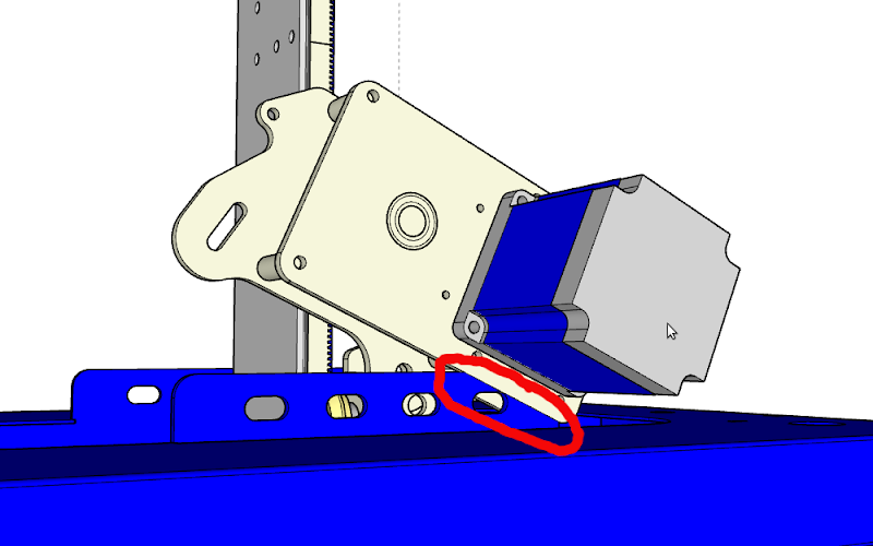 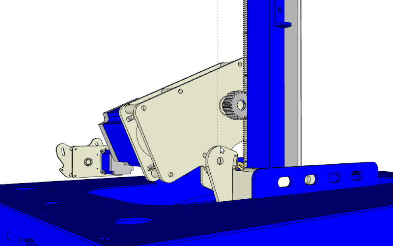 I made a try by placing it upside down... 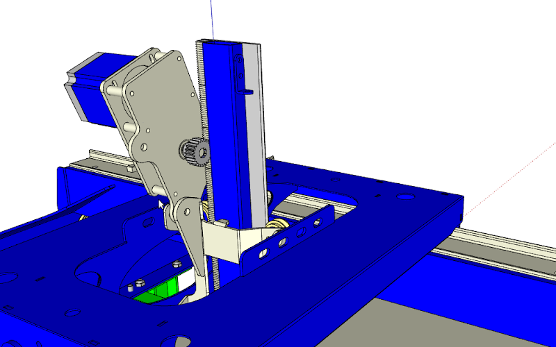  I think it could work upside down but I would be beter to design one big plate specialy for the Z axis. Is there other options that I have not seen? What do you think ? Hardouin Last edited by Hardouin; Fri 02 November 2012 at 09:49..
|
 |
|
|
 Similar Threads
|
||||
| Thread | Thread Starter | Forum | Replies | Last Post |
| Belt reduction box build T5 16 to 60 | linus1 | Driving Mechanisms: Rack/pinion, gears, screws, belts & chains | 3 | Sun 25 July 2010 08:26 |
| Belt reduction installed, cutting metals - Big Lake, MN | chopper | MechMates already cutting | 61 | Mon 23 November 2009 23:02 |
| Has dust foot, belt reduction and plastic wheels #22 - Midrand, S. Africa | MariusL | MechMates already cutting | 124 | Fri 23 October 2009 03:33 |
| Trying smaller motors with belt reduction #17 - Sao Caetano do Sul, SP, Brasil | YRD | MechMates already cutting | 178 | Sat 04 July 2009 08:59 |
| Off the shelf belt drive? | myozman | Motors & their mountings | 2 | Mon 22 June 2009 19:41 |


